LiftMaster TDC Installation Manual - English French Spanish - Page 28
Wiring Diagram
 |
View all LiftMaster TDC manuals
Add to My Manuals
Save this manual to your list of manuals |
Page 28 highlights
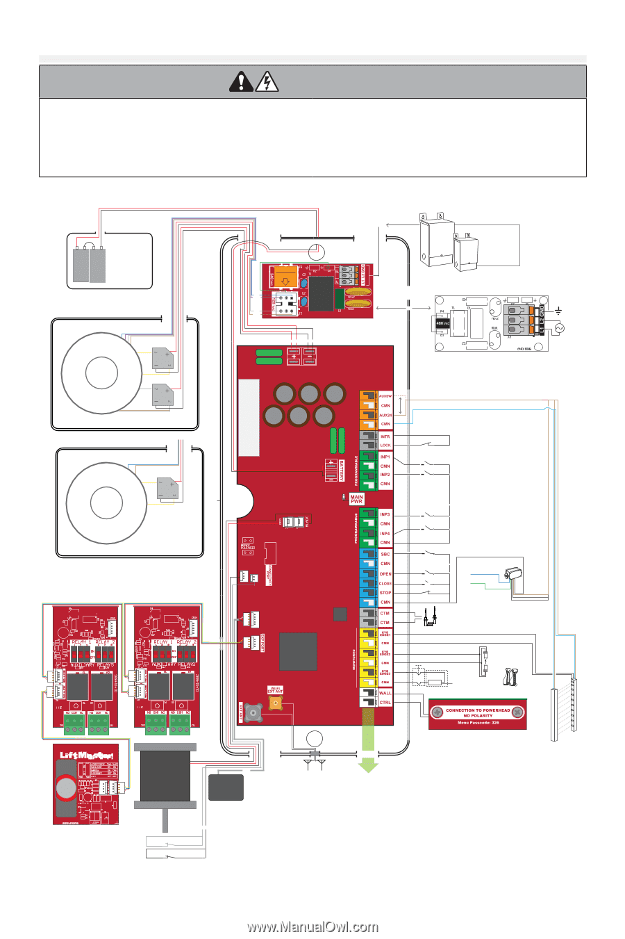
Wiring Diagram WARNING To prevent possible SERIOUS INJURY or DEATH: For continued protection against fire: • Disconnect electric power and/or battery BEFORE • Replace ONLY with fuse of same type and rating. WARNING installing, performing ANY adjustments, or maintenaince. Installation and ALL maintainance MUST be perfoTorpmreveendt pbosysibale tSrEaRIiOnUSeIdNJUdRYooor DrEsATyHs: tems technician. Disconnect electric power and/or battery BEFORE installing, performing ANY adjustments, or maintenance. Installation and ALL maintenance MUST be performed by a trained door systems technician. For continued protection against fire: Replace ONLY with fuse of same type and rating BATTERY BOX +- +- 24Vdc Battery Accessory SKUs: DC45AH- 4.5Ah Batteries DC7AH- 7.0Ah Batteries TRANSFORMER BOX, 1200 Orange Rectifier Transformer Orange Rectifier White White 1200 Model: Two Rectifiers TRANSFORMER BOX, 700 Transformer Orange Rectifier Orange 700 Model: One Rectifier Optional Accessories Motor E-BOX 30 30 No polarity Factory Wired Conduit Black Red Battery Power Conduit AC Input Field Wiring Conduit WARNING Observe Voltage Blue Purple Gray Brown 120V AC or 240V AC EMI FILTER Plug transformer connector into the appropriate voltage that matches the applied AC voltage OR Optional Stepdown Transformer XF208VDC and XF600VDC To use 3-Phase Power, tap any two phase legs. Use proper phase balancing. 600VAC to 120VAC OR 208VAC to 120VAC 480V AC on 480V EMI FILTER Red Red Black Black 30 30 Replaceable 30A Automotive Fuses DC Input from Transformer/Rectifier (One pair for 700, two pairs for 1200) CLASS 2 SUPPLY +24V 480V comes factory wired Accessories may connect to the regular or switched port. Switched is turned off at loss of AC to preserve battery life. ACCESSORY POWER 24VDC, 1A Brown Blue DRY CONTACT NOTE: INTR LOCK jumper MUST be removed if switch is added. BRAKE FUSE HOIST Motor Power Jumpers must be placed if cables are not connected ENCODER Gray Encoder Module Factory Wired Conduit Battery Power Conduit Field Wiring Conduit Ancillary (non-monitored) devices and dry contact inputs NO/NC. SBC OPEN CLOSE STOP NOTE: STOP - CMN jumper MUST be removed if a 3-Button Station is added. Close - Output 2 (Blue) Open - Output 1 (Green) Black 50-HERK2 CABLE TENSION MONITORS Resistive Edge White/Black To EYE/EDGE White To CMN Photo Eyes CPS-U, CPS-UN4, CPS-OPEN4, OES-RD16 LC36M Brown Blue White/Black White Tx Rx Light Curtain LC36M Brake (Phase 2) Hoist Switch Gray Black 28
-
 1
1 -
2
-
3
-
4
-
5
-
6
-
7
-
8
-
9
-
10
-
11
-
12
-
13
-
14
-
15
-
16
-
17
-
18
-
19
-
20
-
21
-
22
-
 23
23 -
 24
24 -
 25
25 -
 26
26 -
 27
27 -
 28
28 -
 29
29 -
 30
30 -
 31
31 -
 32
32 -
 33
33 -
34
-
35
-
36
-
37
-
38
-
39
-
40
-
41
-
42
-
43
-
44
-
45
-
46
-
47
-
48
-
49
-
50
-
51
-
52
-
53
-
54
-
55
-
56
-
57
-
58
-
59
-
60
-
61
-
62
-
63
-
64
-
65
-
66
-
67
-
68
-
69
-
70
-
71
-
72
-
73
-
74
-
75
-
76
-
77
-
78
-
79
-
80
-
81
-
82
-
83
-
84
-
85
-
86
-
87
-
88
-
89
-
90
-
91
-
92
-
93
-
94
-
95
-
96
-
97
-
98
-
99
-
100
-
101
-
102
-
103
-
104
-
105
-
106
-
107
-
108
-
109
-
110
-
111
-
112
-
113
-
114
-
115
-
116
-
117
-
118
-
119
-
120
-
121
-
122
-
123
-
124
-
125
-
126
-
127
-
128
-
129
-
130
-
131
-
132
-
133
-
134
-
135
-
136
-
137
-
138
-
139
-
140
-
141
-
142
-
143
-
144
-
145
-
146
-
147
-
148
-
149
-
150
-
151
-
152
-
153
-
154
-
155
-
156
-
157
-
158
-
159
-
160
-
161
-
162
-
163
-
164
-
165
-
166
-
167
-
168
-
169
-
170
-
171
-
172
-
173
-
174
-
175
-
176
-
177
-
178
-
179
-
180
-
181
-
182
-
183
-
184
-
185
-
186
-
187
-
188
-
189
-
190
-
191
-
192
-
193
-
194
-
195
-
196
-
197
-
198
-
199
-
200
-
201
-
202
-
203
-
204
-
205
-
206
-
207
-
208
-
209
-
210
-
211
-
212
-
213
-
214
-
215
-
216
 |
 |