HP ZBook Studio x360 Maintenance and Service Guide - Page 76
Display assembly, Phillips M2.5×4.5 screws
 |
View all HP ZBook Studio x360 manuals
Add to My Manuals
Save this manual to your list of manuals |
Page 76 highlights
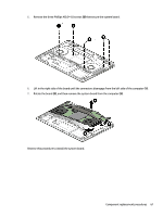
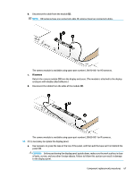
Display assembly NOTE: The Dream Color display assembly and touch display assemblies are spared only as whole unit assemblies. Non-touch display assemblies are spared at the subcomponent level only. For non-touch display assembly spare part information, see the individual removal subsections. Description 15.6-in, UHD, UWVA, Dream Color display assembly not equipped with a camera 15.6-in, UHD, UWVA, Dream Color display assembly equipped with a camera Spare part number L28663-001 L28664-001 To remove the display assembly and access display assembly subcomponents, follow these steps: 1. Turn off the computer. If you are unsure whether the computer is off or in Hibernation, turn the computer on, and then shut it down through the operating system. 2. Disconnect the power from the computer by unplugging the power cord from the computer. 3. Disconnect all external devices from the computer. 4. Remove the bottom cover (see Bottom cover on page 31). 5. Remove the battery (see Battery on page 33). Remove the display assembly: 1. Remove the two Phillips M2.0×3.0 screws (1) from the display cable connector bracket. 2. Remove the bracket (2), and then disconnect the display cable from the system board (3). 3. Disconnect the antennas from the WLAN antenna posts (4). 4. Disconnect the camera cable from the system board (5). Brackets are available in the Bracket Kit using spare part number L28674-001. 5. Remove the five Phillips M2.5×4.5 screws (1) that secure the display to the computer. 64 Chapter 5 Removal and replacement procedures for authorized service provider parts
-
 1
1 -
2
-
3
-
4
-
5
-
6
-
7
-
8
-
9
-
10
-
11
-
12
-
13
-
14
-
15
-
16
-
17
-
18
-
19
-
20
-
21
-
22
-
23
-
24
-
25
-
26
-
27
-
28
-
29
-
30
-
31
-
32
-
33
-
34
-
35
-
36
-
37
-
38
-
39
-
40
-
41
-
42
-
43
-
44
-
45
-
46
-
47
-
48
-
49
-
50
-
51
-
52
-
53
-
54
-
55
-
56
-
57
-
58
-
59
-
60
-
61
-
62
-
63
-
64
-
65
-
66
-
67
-
68
-
69
-
70
-
 71
71 -
 72
72 -
 73
73 -
 74
74 -
 75
75 -
 76
76 -
 77
77 -
 78
78 -
 79
79 -
 80
80 -
 81
81 -
82
-
83
-
84
-
85
-
86
-
87
-
88
-
89
-
90
-
91
-
92
-
93
-
94
-
95
-
96
-
97
-
98
-
99
-
100
-
101
-
102
-
103
-
104
-
105
-
106
-
107
-
108
-
109
-
110
-
111
-
112
-
113
-
114
-
115
-
116
-
117
-
118
-
119
-
120
-
121
-
122
-
123
-
124
-
125
-
126
-
127
-
128
-
129
-
130
-
131
-
132
-
133
-
134
-
135
-
136
-
137
-
138
-
139
-
140
-
141
-
142
-
143
-
144
-
145
-
146
-
147
-
148
-
149
-
150
-
151
-
152
-
153
-
154
-
155
-
156
-
157
-
158
-
159
-
160
-
161
-
162
-
163
-
164
-
165
-
166
-
167
-
168
-
169
-
170
-
171
-
172
-
173
-
174
-
175
-
176
-
177
-
178
-
179
-
180
-
181
-
182
-
183
-
184
-
185
-
186
-
187
-
188
-
189
 |
 |
