HP ZBook Studio x360 Maintenance and Service Guide - Page 158
Multi-pin vertical insert connector LVDS cable to system board, tool under
 |
View all HP ZBook Studio x360 manuals
Add to My Manuals
Save this manual to your list of manuals |
Page 158 highlights
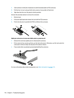
1. Slide connector evenly into receptacle on same horizontal plane as PCB connector. 2. Pull lock bar to insert and push both side connector horizontally to firmly lock. 3. Tape down lock bar over the panel to hold in position. Reverse the procedure above to remove the connector: 1. Remove tape. 2. Pull up bar (pull tape) and release the lock with the PCB connector. 3. Pull to the direction in parallel with PCB to withdraw the connector. Multi-pin vertical insert connector (LVDS cable to system board) ● Remove the connector gasket prior to removing the connector. ● If the connector has a plastic pull tab, use the tab to disconnect. Otherwise, use flat tool under the connector to remove evenly. Do not pull on the cable to remove. ● Press evenly when reseating/reconnecting/installing the connector. For more information about cable management, see Cable management on page 144. 146 Chapter 6 Troubleshooting guide
-
 1
1 -
2
-
3
-
4
-
5
-
6
-
7
-
8
-
9
-
10
-
11
-
12
-
13
-
14
-
15
-
16
-
17
-
18
-
19
-
20
-
21
-
22
-
23
-
24
-
25
-
26
-
27
-
28
-
29
-
30
-
31
-
32
-
33
-
34
-
35
-
36
-
37
-
38
-
39
-
40
-
41
-
42
-
43
-
44
-
45
-
46
-
47
-
48
-
49
-
50
-
51
-
52
-
53
-
54
-
55
-
56
-
57
-
58
-
59
-
60
-
61
-
62
-
63
-
64
-
65
-
66
-
67
-
68
-
69
-
70
-
71
-
72
-
73
-
74
-
75
-
76
-
77
-
78
-
79
-
80
-
81
-
82
-
83
-
84
-
85
-
86
-
87
-
88
-
89
-
90
-
91
-
92
-
93
-
94
-
95
-
96
-
97
-
98
-
99
-
100
-
101
-
102
-
103
-
104
-
105
-
106
-
107
-
108
-
109
-
110
-
111
-
112
-
113
-
114
-
115
-
116
-
117
-
118
-
119
-
120
-
121
-
122
-
123
-
124
-
125
-
126
-
127
-
128
-
129
-
130
-
131
-
132
-
133
-
134
-
135
-
136
-
137
-
138
-
139
-
140
-
141
-
142
-
143
-
144
-
145
-
146
-
147
-
148
-
149
-
150
-
151
-
152
-
 153
153 -
 154
154 -
 155
155 -
 156
156 -
 157
157 -
 158
158 -
 159
159 -
 160
160 -
 161
161 -
 162
162 -
 163
163 -
164
-
165
-
166
-
167
-
168
-
169
-
170
-
171
-
172
-
173
-
174
-
175
-
176
-
177
-
178
-
179
-
180
-
181
-
182
-
183
-
184
-
185
-
186
-
187
-
188
-
189
 |
 |
