| Section |
Page |
| Copyright |
4 |
| Warning Labels |
12 |
| Safety Interlocks |
12 |
| United States |
14 |
| Canada |
14 |
| European Union |
14 |
| Contents |
17 |
| General Information |
25 |
| System Introduction and Overview |
26 |
| System Features and Configurations |
27 |
| Standard Configurations |
27 |
| Front View |
28 |
| Open View |
28 |
| Side View with System Interfaces |
29 |
| Back View |
29 |
| Electronics Module |
30 |
| Routine Maintenance Items and Consumables Life Expectancy |
31 |
| Control Panel Layout |
32 |
| Menu Map |
35 |
| System Specifications |
36 |
| Physical Dimensions and Clearances |
36 |
| Print Engine (IOT) Functional Specifications |
37 |
| System Electrical Specifications |
38 |
| System Environmental Specifications |
38 |
| Scanner/DADF (IIT) Specifications |
38 |
| Tray and Media Specifications |
40 |
| Duplex Automatic Document Feeder Guidelines |
41 |
| Supported Envelopes |
43 |
| Media Storage Guidelines |
43 |
| Media that May Damage the System |
44 |
| Media Skew Specification Print Engine (IOT) |
44 |
| Media System Skew Specification (IIT/IOT) |
44 |
| Theory of Operation |
45 |
| System Overview |
46 |
| System Summaries |
46 |
| Image Input Terminal (IIT) |
47 |
| Major Components of the DADF and Scanner |
47 |
| Document Feeder Functions |
48 |
| Document Feeder Paper Path and Imaging |
50 |
| Copy/Scan Imaging |
50 |
| Scanner Assembly Functions |
51 |
| Scanner and Document Feeder Calibration |
52 |
| Automatic Calibration |
52 |
| Automatic DADF Calibration |
52 |
| Automatic Scanner Calibration |
53 |
| Manual Calibration |
53 |
| System Electronics |
54 |
| Exit Module (MEP) Board |
55 |
| Scanner Power Supply |
55 |
| Electronics Module |
55 |
| Power Supply Diagram (Electronics Module) |
58 |
| Image Output Terminal (IOT) Sub-Assemblies |
59 |
| Sub-Assemblies of the IOT |
60 |
| Paper Path and Paper Pick |
62 |
| Paper Pick for Tray 1 |
62 |
| Paper Pick for Trays 2 - 4 |
63 |
| 2-Sided (Duplex) Printing |
64 |
| Sensor Locations |
65 |
| System Motors, Solenoids, and Drive |
66 |
| Process Drive |
67 |
| Media Path Drive |
68 |
| The Print Process |
69 |
| Drum Preparation |
70 |
| Printing |
70 |
| Ink Loader |
71 |
| Printhead |
72 |
| Printhead Tilt |
75 |
| Drum Assembly |
78 |
| Transfix System |
80 |
| Drum Maintenance System |
81 |
| Purge System |
82 |
| Transfixing and Exiting |
84 |
| Transfix and Print Speeds |
88 |
| Configuration Card Personality Parameters |
89 |
| Error Messages and Codes |
93 |
| Introduction |
94 |
| Power-Up Error Messages and LED Codes |
95 |
| BIST Error Reporting |
95 |
| POST Error Reporting |
96 |
| PEST Error Reporting |
99 |
| Fault Code Error Message Troubleshooting |
100 |
| Fault Code Error Reporting |
100 |
| Interpreting Fault Codes |
100 |
| 1,000.4x Error - 525-Sheet Feeder Faults |
101 |
| 2,0XX.4x Error - I/O Circuit Board Fault |
102 |
| 2,0XX.6x Errors - I/O Board Program Faults |
102 |
| 3,0XX.6x - IPC Program Faults |
102 |
| 4,0XX.4x Errors - Process Control System Fault |
103 |
| 4,0XX.6x Process Control Software Fault |
105 |
| 5,0XX.4x Errors - Y-Axis Sub-System Fault |
106 |
| 5,0XX.6x Errors - Program Faults |
106 |
| 6,0XX.4x Errors - X-Axis Fault |
107 |
| 6,0XX.6x Errors - Program Faults |
107 |
| 7,0XX.4x Errors - Process Motor Gearbox Faults |
108 |
| 7,0XX.6x Errors - Program Faults |
111 |
| 8,0XX.xx Error - Wiper/Media Path Gearbox Faults |
112 |
| 8,0XX.6x Errors - Program Faults |
113 |
| 9,0XX.xx Errors - Ink Loader Faults |
114 |
| 9,009.44 and 900X.6x |
114 |
| 11,0XX.xx Errors - Electronics Module Interface Fault |
115 |
| 11,100.60 - Temperature Error |
116 |
| 12,000.60 Errors - Program Faults |
116 |
| 13,0XX.xx Errors - Thermal Faults |
116 |
| 13,000.6x Errors - Program Faults |
124 |
| 19,0XX.xx Errors - Printhead Calibration faults. |
125 |
| 19,0XX.6x - Errors |
125 |
| 21,000.69 Errors - Diagnostic Code Version Mismatch |
125 |
| 22,0XX.6x Errors - Jam Codes |
125 |
| 23,0XX.6x Errors - NVRAM Fault |
125 |
| 26,0XX.6x Errors - Printing Faults |
125 |
| 27,0XX.6x Errors - Profile Library |
126 |
| 29,0XX.6x Errors - Jam Manager |
126 |
| 31,0XX.4x Errors - Mechanical Initialization Jam |
126 |
| 31,0XX.6x Errors - Program Faults |
126 |
| 33,0XX.xx Errors - Tray Manager Device Faults |
127 |
| 34,0XX.xx Errors - Printhead NVRAM Faults |
127 |
| 36,000.40 Errors - Drum Maintenance Faults |
128 |
| 36,001.67 Errors |
128 |
| 37,0XX.xx Errors - PEST Faults |
129 |
| 39,0XX.xx Errors - Document Feeder / Scanner Unit Faults |
138 |
| 3-Digit Jam Codes |
141 |
| Jam Code Definition Table |
142 |
| General Troubleshooting |
159 |
| Introduction |
160 |
| Hidden Service Menu |
160 |
| Service Diagnostics |
162 |
| Service Diagnostics Menu Functions |
162 |
| Important Information While Performing Service Diagnostics |
162 |
| Entering Service Diagnostics |
163 |
| From Customer Mode to Diagnostics: |
163 |
| From System OFF to Diagnostics: |
163 |
| Service Diagnostic Menu Definition Tables |
164 |
| Service Diagnostic Print Engine Menu Functions |
169 |
| Check Menu / Activators Definition Tables |
173 |
| Check / Activators Menu |
173 |
| Check Shafts Menu |
176 |
| Check Fans Menu |
182 |
| Check Heaters Menu |
183 |
| Check Paper Path Menu |
185 |
| Check Drive Menu |
193 |
| Check Drum Menu |
198 |
| Check Motors Menu |
203 |
| Check Misc Menu |
206 |
| System Power-Up Sequence |
212 |
| Mechanical Initialization of the Print Engine |
213 |
| Head Cleaning Cycle Performance |
215 |
| Electrical Troubleshooting |
216 |
| Electronics Module |
216 |
| Document Feeder Lamp Does Not Turn ON |
217 |
| Document Feeder Does Not Feed Media |
217 |
| Scanner Scanhead Does Not Move |
218 |
| Scanhead Motion is Not Smooth and Continuous |
218 |
| Scanner Lamp Does Not Turn On |
218 |
| Control Panel is Malfunctioning |
218 |
| System Continuously Resets or Resets Unexpectedly |
219 |
| Control Panel Is Blank and the PS and PE Indicators are Flashing an Error Code |
219 |
| Exit Module (MEP) is Malfunctioning |
220 |
| System Fails to Power-Up |
220 |
| System Energy Star Mode Troubleshooting |
222 |
| System Reports Missing Maintenance Kit |
223 |
| System Reports Missing Waste Tray |
223 |
| System Features Not Available |
223 |
| 525-Sheet Feeder Does Not Function |
224 |
| Non-Specific Electronics Failure |
225 |
| Verifying Scanner Power Supply Operation |
228 |
| Verifying Power Supply Operation - Print Engine |
229 |
| Measuring AC Power Supply Voltages |
230 |
| Detecting condition of Fuse F2 and F3 |
230 |
| Measuring DC Power Supply Voltages |
231 |
| Ensuring Ground Integrity |
231 |
| Testing Motor and Solenoid Resistances |
233 |
| Paper Path and Media-Based Problems |
234 |
| Media-Based Problems |
234 |
| Paper-Pick Errors - Trays 2, 3, and 4 |
234 |
| Paper-Pick Errors - Tray 1 |
235 |
| Document Feeder Pick Problems |
235 |
| Preheater and Transfix Jams |
235 |
| Checking the Process and Media Path Drive |
236 |
| Media Skews Passing Through the Paper Path |
236 |
| Operating System and Application Problems |
237 |
| Testing Communications Ports |
237 |
| Ethernet Port Verification |
237 |
| Ethernet Port Verification for Default Assigned IP Address 169.254.xxx.xxx |
238 |
| USB Port Verification |
239 |
| Network Problems |
239 |
| To print an Event Log or Runtime Log: |
239 |
| Obtaining Serial Back Channel Trace |
240 |
| Image-Quality Troubleshooting |
241 |
| Image-Quality Problems Overview |
242 |
| Service Technician RIP Procedure |
243 |
| Isolating a Copy/Scan Malfunction to the Scanner/DADF |
243 |
| Before troubleshooting image-quality problems: |
243 |
| DADF Image-Quality Problems |
244 |
| Dark Streaks on the Copied Image |
244 |
| Skewed Copy Image |
245 |
| Copy Image is Lighter/Darker than the Original |
245 |
| Fuzzy Text/Image |
246 |
| Copied Image Colors Do Not Match the Original |
247 |
| Scanner Image Quality Problems |
248 |
| Dark Streaks on the Copied Image |
248 |
| Copied Image is Skewed |
248 |
| Copied Image is Lighter/Darker than the Original |
248 |
| Copy Image Colors Do Not Match the Original |
249 |
| Fuzzy Text/Image |
250 |
| Diagnosing IOT (Print Engine) Print-Quality Problems |
251 |
| Random Light Stripes |
252 |
| Predominate Light Stripes |
253 |
| Smudges or Smears |
254 |
| The Printed Image Is Too Light or Too Dark |
255 |
| No Image is Being Printed |
255 |
| Color is Uneven or Color is Wrong |
256 |
| Streaks or Lines Down the Print |
257 |
| Scratches or Marks Parallel to the Long Axis of Printing, Particularly with Transparencies |
259 |
| There is ink on the White Portion of the Printed Page |
261 |
| Fuzzy Text |
262 |
| Poor Primary Color Fills |
264 |
| Ghosting |
265 |
| Poor Small Text Resolution |
266 |
| Vertical Lines Appear Wavy |
267 |
| Oil Streaks on Print |
268 |
| Incomplete Image Transfer to Paper |
269 |
| Ink Smears on First Printed Side of Duplex Print |
270 |
| Repeating Print Defects on Print |
271 |
| White Stripes (Pinstripes) |
272 |
| Wrinkling |
273 |
| Image is Offset or Cut-Off |
274 |
| Poor Ink Adhesion, Poor Image Durability |
274 |
| Analyzing Service Test Prints |
275 |
| Test Print Examples |
275 |
| 1: Weak/Missing Jet |
275 |
| 2: X-Axis Motion (Drop Mass Evaluation) |
276 |
| 3: Color Bands, RGBK Dither |
276 |
| 4: Reverse Text |
277 |
| 5: Big Bands OHP |
278 |
| 6: Gray Fill, Dot Size Uniformity |
279 |
| 7: Manuf. Five Duplex GSF |
279 |
| 8: YMCKRGB Solid Fills |
280 |
| 9: Drum Seal |
280 |
| 10: Manuf. Paper Path |
280 |
| 11: Head-to-Drum Check |
281 |
| 12: Manuf X-Axis (Scanner) |
281 |
| 13-19: Black, Red, Green, Blue, Cyan, Magenta, and Yellow Solid Fills |
282 |
| 20: OHP Color Bands |
282 |
| 21: Primary Solid Fills 10x |
283 |
| 22: Manuf. Skew Margins |
284 |
| 23: Manuf. Banding |
285 |
| 24: Head Roll |
285 |
| 25: Head Height |
285 |
| 26: X Dot Position |
285 |
| 27: Y Dot Position |
285 |
| 28: Chase Pages |
285 |
| 29: Oil Bar Chase |
285 |
| 30: Purge Efficiency |
285 |
| 31: Cleaning (Chase) Page |
286 |
| Adjustments and Calibrations |
287 |
| System Alignments and Adjustments |
288 |
| Wiper Alignment |
288 |
| Print Engine Component Home Positions and Indicators |
290 |
| Homing the Printhead Wiper |
290 |
| Homing the Head Tilt Gear |
291 |
| When the Printhead Is NOT Installed |
291 |
| Homing the Process Gear Drive Train |
294 |
| Manual DADF to Scanner Calibration |
295 |
| Starting the Calibration Procedure |
295 |
| Scanner Platen Steps |
296 |
| Document Feeder Steps |
297 |
| Jet Substitution Mode |
298 |
| Enabling Jet Substitution Mode |
298 |
| Disabling Jet Substitution Mode |
299 |
| Resetting NVRAM |
299 |
| Cleaning and Maintenance |
301 |
| Inspection |
302 |
| System Self-Maintenance |
303 |
| Printhead Maintenance Cycle (Eliminate Light Stripes) |
303 |
| Paper Preheater Cleaning (Remove Print Smears) |
304 |
| Transfix Roller Oiling |
304 |
| Drum Cleaning - Chase Page |
304 |
| Service Cleaning and Maintenance Procedures |
305 |
| Supplies Required |
305 |
| Cleaning for Print-Quality Problems |
306 |
| Scan or Copy Print-Quality Problem |
306 |
| Light Stripes or Missing Colors |
306 |
| Ink Smears, Oil Spots, or Random Ink Streaks |
306 |
| Media Jams and Paper Pick Cleaning Procedures |
307 |
| Pick Roller Cleaning Methods |
307 |
| Tray 1 Pick Rollers |
307 |
| Cleaning the Drum Temperature Sensor |
308 |
| Maintenance Kit |
309 |
| Maintenance Kit Life |
309 |
| Waste Tray |
309 |
| Lubrication |
310 |
| Service Parts Disassembly |
311 |
| Overview |
312 |
| Standard Orientation of the System |
312 |
| General Notes on Disassembly |
313 |
| Special Notes Regarding Screws Used in This Equipment. |
313 |
| Notations in the Disassembly Text |
313 |
| Image Input Terminal (DADF and Scanner) |
314 |
| Duplex Automatic Document Feeder |
314 |
| DADF Front Cover |
315 |
| Scanner Assembly |
316 |
| Control Panel |
317 |
| Image Output Terminal (Print Engine) |
317 |
| Covers |
318 |
| Output Paper Tray Assembly |
318 |
| Front Door / Tray 1 Assembly |
320 |
| Right and Left Side Covers |
321 |
| Rear Cover and EMI Shield |
322 |
| Imaging |
323 |
| Ink Loader Assembly |
323 |
| Replacement Notes: |
323 |
| Y-Axis Drum Belt, Y-Axis Tension Spring, and Y-Axis Motor Assembly |
324 |
| Replacement Notes: |
325 |
| Printhead Assembly, Right and Left Printhead Restraints |
326 |
| Replacement Notes: |
331 |
| X-Axis Bias Spring |
333 |
| Replacement Note: |
333 |
| Printhead Wiper |
334 |
| Replacement Note: |
335 |
| Media Release Blade (Stripper) Carriage Assembly and Transfix Roller |
336 |
| Paper Preheater and Deskew Assembly |
337 |
| Replacement Note: |
338 |
| Duplex Roller |
339 |
| Transfix Load Module |
340 |
| Replacement Notes: |
343 |
| Transfix Camshaft Assembly |
344 |
| Drum Maintenance Camshaft Assembly |
345 |
| Replacement Notes: |
345 |
| Drum Maintenance Pivot Plate Assembly |
346 |
| Drum Assembly |
347 |
| Replacement Notes: |
348 |
| Purge Pressure Pump |
351 |
| Paper Path |
352 |
| Exit Module Assembly (MEP) |
352 |
| Replacement Note: |
354 |
| Paper Guides |
354 |
| Inner Simplex |
354 |
| Replacement Note: |
354 |
| Lower Inner Duplex |
354 |
| Lower Exit-Guide Assembly with Strip Flag |
354 |
| Upper Duplex Guide with Solenoid |
355 |
| Replacement Notes: |
357 |
| Take Away Roller |
358 |
| Pick Assembly |
359 |
| Replacement Note: |
360 |
| Tray Lift Motor |
361 |
| Replacement Note: |
361 |
| Motors, Gears, Solenoids, Clutches, and Fans |
362 |
| Media Drive Gearbox with Two Clutches and Solenoid |
362 |
| Replacement Note: |
363 |
| Tray 1 (MPT) Pick Solenoid |
364 |
| Process Drive Motor and Gearbox |
365 |
| Replacement Notes: |
366 |
| X-Axis Motor Assembly |
367 |
| Replacement Note: |
367 |
| Head Tilt Compound Gear |
368 |
| Replacement Notes: |
368 |
| Electronics |
369 |
| Scanner Power Supply |
369 |
| Exit Module (MEP) Board |
370 |
| Electronics Module |
371 |
| Replacement Note: |
372 |
| Back Frame and Printer Stabilizer |
373 |
| Wave Amp Board |
375 |
| Replacement Note: |
375 |
| I/O Board |
376 |
| Replacement Note: |
376 |
| Drum Heater Relay Board |
377 |
| Replacement Note: |
377 |
| NVRAM Replacement |
378 |
| Parts Lists |
379 |
| Serial Number Format |
380 |
| The serial number is coded as follows: |
380 |
| Serial Number Example: |
380 |
| Using the Parts List |
381 |
| Covers |
382 |
| Imaging |
384 |
| Paper Path |
386 |
| Motors, Gears, Solenoids, Clutches, Sensors, Fans and Backframe |
388 |
| Electronics Module, Circuit Boards and Cables |
390 |
| Sensors and Flags (Actuators) |
392 |
| Xerox Supplies |
394 |
| Wiring Diagrams |
397 |
| Plug/Jack Locator Table |
398 |
| Scanner/DADF Functional Diagrams |
401 |
| Main Block Wiring Diagram |
402 |
| Main Block Wiring Diagram (Continued) |
403 |
| Scanner/Exit Module Power Supply and MEP (Exit Module) Board |
404 |
| Right-Side Wiring Diagram |
405 |
| Right-Side Wiring Diagram (Continued) |
406 |
| Left-Side Wiring Diagram |
407 |
| Left-Side Wiring Diagram (Continued) |
408 |
| Inside Front Wiring Diagram |
409 |
| Inside Top Wiring Diagram |
410 |
| Inside Top Wiring Diagram (continued) |
411 |
| Electronics Module |
412 |
| Appendix |
413 |
| Control Panel Menu Map |
414 |
| Control Panel Menu Map -continued- |
415 |
| Control Panel Menu Map -continued- |
416 |
| Media Margin Specification Table |
417 |
| Paper Weight Equivalence Table |
418 |
 1
1 354
354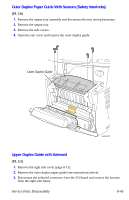 355
355 356
356 357
357 358
358 359
359 360
360 361
361 362
362 363
363 364
364