2004 Ducati Monster S4R Owners Manual - Page 147
2004 Ducati Monster S4R Manual

Page 147 highlights
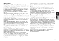
E Legend of the wiring diagram of electric system/ignition 1) R.H. switch 2) Transponder antenna 3) Key-operated switch 4) Ignition relay 5) Fuse box 6) Starter motor 7) Starter solenoid 8) Battery 9) Regulator protection fuse 10) Regulator 11) Generator 12) Rear, right-turn indicator 13) Tail light 14) Number plate light 15) Rear, left-turn indicator 16) Fuel tank 17) Self-diagnosis connector 18) Speed sensor 19) Horizontal cylinder coil 20) Vertical cylinder coil 21) Horizontal cylinder spark plug 22) Vertical cylinder spark plug 23) Horizontal cylinder injector 24) Vertical cylinder injector 25) Throttle position sensor 26) Timing/engine rpm sensor 27) Side stand switch 28) 5.9 M CPU 29) Injection relay 72 30) Neutral light switch 31) Oil pressure switch 32) Rear STOP light switch 33) Front STOP light switch 34) L.H. switch 35) Air temperature/pressure sensor 36) Instruments 37) Front left-turn indicator 38) Horn 39) Headlamp 40) Front right-turn indicator 41) CPU water temperature sensor 42) Instrument water temperature sensor 43) Clutch switch 44) R.H. fan 45) L.H. fan Wire color coding B Blue W White V Violet Bk Black Y Yellow R Red Lb Light blue Gr Grey G Green Bn Brown O Orange P Pink
-
 1
1 -
2
-
3
-
4
-
5
-
6
-
7
-
8
-
9
-
10
-
11
-
12
-
13
-
14
-
15
-
16
-
17
-
18
-
19
-
20
-
21
-
22
-
23
-
24
-
25
-
26
-
27
-
28
-
29
-
30
-
31
-
32
-
33
-
34
-
35
-
36
-
37
-
38
-
39
-
40
-
41
-
42
-
43
-
44
-
45
-
46
-
47
-
48
-
49
-
50
-
51
-
52
-
53
-
54
-
55
-
56
-
57
-
58
-
59
-
60
-
61
-
62
-
63
-
64
-
65
-
66
-
67
-
68
-
69
-
70
-
71
-
72
-
73
-
74
-
75
-
76
-
77
-
78
-
79
-
80
-
81
-
82
-
83
-
84
-
85
-
86
-
87
-
88
-
89
-
90
-
91
-
92
-
93
-
94
-
95
-
96
-
97
-
98
-
99
-
100
-
101
-
102
-
103
-
104
-
105
-
106
-
107
-
108
-
109
-
110
-
111
-
112
-
113
-
114
-
115
-
116
-
117
-
118
-
119
-
120
-
121
-
122
-
123
-
124
-
125
-
126
-
127
-
128
-
129
-
130
-
131
-
132
-
133
-
134
-
135
-
136
-
137
-
138
-
139
-
140
-
141
-
 142
142 -
 143
143 -
 144
144 -
 145
145 -
 146
146 -
 147
147 -
 148
148 -
 149
149 -
 150
150 -
 151
151 -
 152
152 -
153
-
154
-
155
-
156
-
157
-
158
-
159
-
160
-
161
-
162
-
163
-
164
-
165
-
166
-
167
-
168
-
169
-
170
-
171
-
172
-
173
-
174
-
175
-
176
-
177
-
178
-
179
-
180
-
181
-
182
-
183
-
184
-
185
-
186
-
187
-
188
-
189
-
190
-
191
-
192
-
193
-
194
-
195
-
196
-
197
-
198
-
199
-
200
-
201
-
202
-
203
-
204
-
205
-
206
-
207
-
208
-
209
-
210
-
211
-
212
-
213
-
214
-
215
-
216
-
217
-
218
-
219
-
220
-
221
-
222
-
223
-
224
-
225
-
226
-
227
-
228
-
229
-
230
-
231
-
232
-
233
-
234
-
235
-
236
-
237
-
238
-
239
-
240
-
241
-
242
-
243
-
244
-
245
-
246
-
247
-
248
-
249
-
250
-
251
-
252
-
253
-
254
-
255
-
256
-
257
-
258
-
259
-
260
-
261
-
262
-
263
-
264
-
265
-
266
-
267
-
268
-
269
-
270
-
271
-
272
-
273
-
274
-
275
-
276
-
277
-
278
-
279
-
280
-
281
-
282
-
283
-
284
-
285
-
286
-
287
-
288
-
289
-
290
-
291
-
292
-
293
-
294
-
295
-
296
-
297
-
298
-
299
-
300
-
301
-
302
-
303
-
304
-
305
-
306
-
307
-
308
-
309
-
310
-
311
-
312
-
313
-
314
-
315
 |
 |
