Denon AVR-4306 Owners Manual - Page 9

Display, Front panel - 7 1 channel receiver

Page 9 highlights

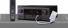
Getting Started Part names and functions Front panel For details on the functions of these parts, refer to the pages given in parentheses ( ). !6 !5 !4 !3 !2 !1 !0 Display !4 !3 !2 Getting Started !1 !0 o i u y #@71 !7 !8 !9 @0 #@72@#36@#45@#54 @#63 @#72 @#81@#90 #0 #6#5 #4#3#2 #1 qw e r t y uio q Power ON/STANDBY button 10) w Power indicator 10) e Power switch 10, 64) r Headphones jack (PHONES 26) t V.AUX INPUT terminals 17) y SETUP MIC jack 10) u USER MODE 1 button 36) i USER MODE 2 button 36) o USER MODE 3 button 36) !0 MASTER VOLUME control knob 25) !1 Master volume indicator 25) !2 Display !3 MultEQ XT indicator 28) !4 NIGHT indicator 31) !5 Remote control sensor 3) !6 FUNCTION knob 25) !7 SOURCE button 25) !8 TUNING PRESET button 40) !9 ZONE2/3/REC SELECT button 62, 64) @0 VIDEO SELECT button 26) @1 NIGHT button 31) @2 ROOM EQ button 28) @3 PURE DIRECT button 30) @4 DIRECT/STEREO button 30) @5 STANDARD button 25) @6 DSP SIMULATION button 37) @7 CH SELECT/ENTER button 39) @8 SURROUND PARAMETER button 31) @9 USB connector 50) #0 iPod connector 44) #1 STATUS button 27) #2 CURSOR button 11) #3 SYSTEM SETUP button 11) #4 EXT. IN button 26) #5 ANALOG button 28) #6 INPUT MODE button 26) qw e rt q Input signal indicator The respective indicator will light corresponding to the input signal. w Input signal channel indicator The channels included in the input source will light. This lights when the digital signal is inputted. e Information display This displays the surround mode, function name or setting value, etc. r Output signal channel indicator The audio channels that can be output light. t Speaker indicator This lights corresponding to the settings of the surround speakers of the various surround modes. y Master volume indicator This displays the volume level. The Setup item number is displayed in System Setup. u MULTI (zone) indicator ZONE2 mode is selected in ZONE2/REC SELECT. i Recording output source indicator REC OUT mode is selected in ZONE2/REC SELECT. o DENON LINK indicator This lights during playback in a DENON LINK connection. !0 AL24 indicator The AL24 indicator lights when the PURE DIRECT, DIRECT, STEREO, MULTI CH PURE DIRECT, MULTI CH DIRECT, MULTI CH IN mode is selected in the PCM input signal. !1 Input mode indicator This lights corresponding to the setting of the input mode. !2 AUTO indicator This lights when the broadcast station is selected in the AUTO tuning mode. !3 TUNED indicator This lights when an FM/AM broadcast has been received. !4 STEREO indicator This lights when an FM stereo broadcast has been received. 4

  • 1
  • 2
  • 3
  • 4
  • 5
  • 6
  • 7
  • 8
  • 9
  • 10
  • 11
  • 12
  • 13
  • 14
  • 15
  • 16
  • 17
  • 18
  • 19
  • 20
  • 21
  • 22
  • 23
  • 24
  • 25
  • 26
  • 27
  • 28
  • 29
  • 30
  • 31
  • 32
  • 33
  • 34
  • 35
  • 36
  • 37
  • 38
  • 39
  • 40
  • 41
  • 42
  • 43
  • 44
  • 45
  • 46
  • 47
  • 48
  • 49
  • 50
  • 51
  • 52
  • 53
  • 54
  • 55
  • 56
  • 57
  • 58
  • 59
  • 60
  • 61
  • 62
  • 63
  • 64
  • 65
  • 66
  • 67
  • 68
  • 69
  • 70
  • 71
  • 72
  • 73
  • 74
  • 75
  • 76
  • 77
  • 78
  • 79
  • 80
  • 81
  • 82
  • 83
  • 84
  • 85
  • 86
  • 87
  • 88
  • 89
  • 90
  • 91
  • 92
  • 93
  • 94
  • 95
  • 96
  • 97
  • 98
  • 99
  • 100
  • 101
  • 102
  • 103
  • 104
  • 105
  • 106
  • 107
  • 108
  • 109
  • 110
  • 111
  • 112
  • 113
  • 114
  • 115
  • 116
  • 117
  • 118
  • 119
  • 120
  • 121
  • 122
  • 123
  • 124
  • 125
  • 126
  • 127
  • 128
  • 129
  • 130
  • 131
  • 132
  • 133
  • 134
  • 135
  • 136
  • 137
  • 138
  • 139
  • 140
  • 141
  • 142
  • 143
  • 144
  • 145
  • 146

4
Display
Getting Started
Getting Started
y
u
i
o
!
0
!
1
!
2
!
3
!
4
e
r
t
q
w
q
Input signal indicator
The respective indicator will light corresponding
to the input signal.
w
Input signal channel indicator
The channels included in the input source
will light.
This lights when the digital signal is inputted.
e
Information display
This displays the surround mode, function
name or setting value, etc.
r
Output signal channel indicator
The audio channels that can be output light.
t
Speaker indicator
This lights corresponding to the settings of
the surround speakers of the various
surround modes.
y
Master volume indicator
This displays the volume level.
The Setup item number is displayed in
System Setup.
u
MULTI (zone) indicator
ZONE2 mode is selected in ZONE2/REC
SELECT.
i
Recording output source indicator
REC OUT mode is selected in ZONE2/REC
SELECT.
o
DENON LINK indicator
This lights during playback in a DENON LINK
connection.
!
0
AL24 indicator
The AL24 indicator lights when the PURE
DIRECT, DIRECT, STEREO, MULTI CH PURE
DIRECT, MULTI CH DIRECT, MULTI CH IN
mode is selected in the PCM input signal.
!
1
Input mode indicator
This lights corresponding to the setting of
the input mode.
!
2
AUTO indicator
This lights when the broadcast station is
selected in the AUTO tuning mode.
!
3
TUNED indicator
This lights when an FM/AM broadcast has
been received.
!
4
STEREO indicator
This lights when an FM stereo broadcast has
been received.
Part names and functions
Front panel
For details on the functions of these parts, refer to the pages given in parentheses (
).
#
7
#
7
#
6
#
6
#
5
#
5
#
4
#
4
#
3
#
3
#
2
#
2
#
1
#
1
#
0
#
0
#
0
#
0
#
7
#
7
!
6
!
2
!
1
!
0
!
5!
4
@
2
!
3
@
3@
4@
5@
6
@
1
@
7
@
8
@
9
#
0
q
w
e
r
t
u
i
o
#
6
#
5
#
4
#
3
#
1
#
2
y
!
7
@
0
!
9
!
8
q
Power ON/STANDBY button
··············(10)
w
Power indicator
····································(10)
e
Power switch
·································(10, 64)
r
Headphones jack (PHONES)
···············(26)
t
V.AUX INPUT terminals
······················(17)
y
SETUP MIC jack
···································(10)
u
USER MODE 1 button
·························(36)
i
USER MODE 2 button
·························(36)
o
USER MODE 3 button
·························(36)
!
0
MASTER VOLUME control knob
········(25)
!
1
Master volume indicator
·····················(25)
!
2
Display
!
3
MultEQ XT indicator
····························(28)
!
4
NIGHT indicator
···································(31)
!
5
Remote control sensor
··························(3)
!
6
FUNCTION knob
···································(25)
!
7
SOURCE button
···································(25)
!
8
TUNING PRESET button
·····················(40)
!
9
ZONE2/3/REC SELECT button
······(62, 64)
@
0
VIDEO SELECT button
·························(26)
@
1
NIGHT button
·······································(31)
@
2
ROOM EQ button
·································(28)
@
3
PURE DIRECT button
···························(30)
@
4
DIRECT/STEREO button
······················(30)
@
5
STANDARD button
······························(25)
@
6
DSP SIMULATION button
···················(37)
@
7
CH SELECT/ENTER button
·················(39)
@
8
SURROUND PARAMETER button
······(31)
@
9
USB connector
·····································(50)
#
0
iPod connector
·····································(44)
#
1
STATUS button
····································(27)
#
2
CURSOR button
···································(11)
#
3
SYSTEM SETUP button
······················(11)
#
4
EXT. IN button
······································(26)
#
5
ANALOG button
···································(28)
#
6
INPUT MODE button
···························(26)