Panasonic WU-192ME2U9 Technical Data Manual - Page 377
Connection as a Relay Control Unit, Output terminals, Relay Circuit Examples, Alarm Display
 |
View all Panasonic WU-192ME2U9 manuals
Add to My Manuals
Save this manual to your list of manuals |
Page 377 highlights
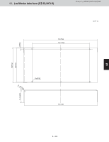
9 3 - 305 8 7 6 5 Connection as a Relay Control Unit The interface adaptor output terminal and input terminal specifications are given below. Use the signals most appropriate for the type of equipment being controlled. (1) Output terminals The interface adaptor provides four styles of ON (set relay) and OFF (reset relay) output signals for use by the equipment being controlled. Select the style appropriate for your application. For more information, see the "Relay Circuit Examples" section. Output style Pulse contact output ON (set) output: a-contact OFF (reset) output: a-contact Contact outputs (relay contact) 1 ON OFF Setting method S002-1: OFF S002-4: OFF S003: NO Pulse contact output ON (set) output: a-contact ON 1 OFF (reset) output: b-contact OFF S002-1: OFF S002-4: OFF S003: NC Pulse contact output ON (set) output: a-contact Both start and stop signals are sourced in turn from the ON (set) relay 1 ON Static contact output (continuous contact) OFF ON OFF OFF S002-1: OFF S002-2: OFF S002-4: ON Only the ON contact output is used. The OFF contact output becomes a local prohibit signal (see 2) S002-1: ON Only the ON contact output is used. The OFF contact output becomes a local prohibit signal (see 2) 1 The pulse width is approximately 0.5 seconds. 2 The output changes according to a signal from the central control unit. Use this signal as needed. Individual permission: OFF (continuous contact) Local prohibit: ON (continuous contact) < Contact capacity > Output ON (set) relay output (CN1, terminals 6 and 7) OFF (reset) relay output (CN1, terminals 8 and 9) Contact capacity (resistive load) 24V AC, 1 A Minimum usable load: 5 V, 100 mA 24V AC, 1 A Minimum usable load: 5 V, 100 mA Caution: Note that the ON (set) relay output and OFF (reset) relay output have different contact capacities. (2) Input terminals Status monitor signals from the equipment being controlled are received by the relay contacts. The local start/stop input uses a pulse style, so connect it to a momentary input device, such as a push switch. Input Operation answer-back input Alarm signal input Terminal numbers 1, 2 1, 3 Input style Usage No-voltage a-contact Monitor the operation (static) (start/stop condition) No-voltage a-contact Monitor general (static) alarms Thermo ON signal input 1, 4 No-voltage a-contact Monitor the load when the thermo is ON, and (static) report to the central control unit Local start/stop input 1, 5 No-voltage a-contact Equipment ON/OFF (pulse) from interface adaptor Circuit contact voltage and current: 12 V DC, 10 mA Caution: When local prohibit (central) is set by the central control unit, the local start/stop input will be ignored. When stopped, the alarm input will be ignored. Continuous contact output (no-voltage contact) Pulse contact output (no-voltage contact) (ON output a-contact + OFF output b-contact) (ON output a-contact + OFF output a-contact) Relay Circuit Examples Style Installed equipment (areas within the dashed lines are the interface adaptor) Pulse contact output (no-voltage contact) Operation circuit Operation circuit 6 8 x 1 7 ON output x 2 x 1 9 OFF output (b-contact) Common 1 x 1 x 2 Operation answer-back 2 Monitor input 6 x 1 7 ON output 8 Common 1 9 x 1 OFF output Operation x 1 (a-contact) answer-back 2 Monitor input (ON output a-contact) Operation circuit 6 7 ON output x 1 The equipment can be connected directly if it requires 24V AC, 1 A or less (inductive load). ON output 6 7 Operation circuit Equipment Input (no-voltage a-contact) COM 1 Operation 2 answer-back Alarm signal 3 Thermo ON signal 4 Local stop/start 5 input Interface adaptor 6 ON output (No-voltage a-contact) 7 COM 1 Operation answer-back 2 x 1 x 2 x 3 SW (ON/OFF) Operation contact Alarm contact Thermo ON contact Local start/stop switch Circulation fan with full heat exchanger External start / stop control input (No-voltage a-contact pulse input) Circulation fan with full heat exchanger Start / stop status output (No-voltage a-contact) Connecting to a circulation fan with a full heat exchanger Notes 1) X1, X2 are auxiliary devices. 2) The interface adaptor OFF output uses the a-contact (S003 set to NO). 3) Switch S002-1 is OFF. Switch S002-4 is OFF. 1) X1 is an auxiliary device. 2) The interface adaptor OFF output uses the b-contact (S003 set to NC). 3) Switch S002-1 is OFF. Switch S002-4 is OFF. 1) X1 is an auxiliary devices. 2) Switch S002-1 is ON. 3) The equipment can be controlled directly (power supply directly shut off) by the ON output if it requires 24V AC, 1 A or less (inductive load). 4) The output will be OFF during a commercial power outage. 5) The OFF output may be used for individual / central selection (will be ON when the central control unit is set to "central", off when the central control unit is set to "individual"). 1) X1, X2, X3 are auxiliary devices; SW is a push switch. 2) If operation answer-back from the equipment is not used, switch S002-2 is ON. In this case, the internal answer-back will be OFF during a commercial power outage. 3) If the answer-back input is unused, it should not be connected. (Only connect inputs that are used.) 1) Switch S002-1 is OFF, switch S002-2 is OFF, switch S002-4 is ON. 2) The circulation fan with full heat exchanger's external start/stop control input uses no-voltage a-contact pulse, and its start/stop condition output uses no-voltage a-contact. Caution: If the central control unit or circulation fan with full heat exchanger remote controller repeatedly and continuously initiates start/stop operations, the circulation fan with full heat exchanger may not be able to recognize the settings. 4 3 2 1 Alarm Display Item Alarm from connected equipment Alarm Meaning An alarm signal was received by the interface adaptor from a connected piece of equipment during operation. Action Investigate the reason for the alarm from the connected equipment, and remove the cause of the alarm. Service display lamps D100 D101 D102 D103 System stop The system is stopped. Not an alarm blink Off Of the items listed above, only the alarm from connected equipment is passed to an upstream central control unit, which will display "C12". If the central control unit does not have an LCD display, then its warning LED will blink. Specifications Power source 24V AC ±15% 50 / 60Hz , 1-PH Power consumption 5.7 W Operating environment 32-104 , 20-80% humidity, indoor only External dimensions 2.5"(63.8mm) (h) x 10.9"(276mm) (w) x 5.4"(136mm) (d) Weight Approx. 2.87lb.(1.3 kg) External dimensions 2.5"(63.8) 0.4"(9.2) 5.0"(126) Unit: in.(mm) 8.8"(224.0) 4.6"(116.4) 5.4"(136.0) Printed in Japan 85464369870010 DC0715-0 Control of 2WAY VRF SYSTEM 10.9"(276) 12. Interface Adaptor (CZ-CAPC2U)
-
 1
1 -
2
-
3
-
4
-
5
-
6
-
7
-
8
-
9
-
10
-
11
-
12
-
13
-
14
-
15
-
16
-
17
-
18
-
19
-
20
-
21
-
22
-
23
-
24
-
25
-
26
-
27
-
28
-
29
-
30
-
31
-
32
-
33
-
34
-
35
-
36
-
37
-
38
-
39
-
40
-
41
-
42
-
43
-
44
-
45
-
46
-
47
-
48
-
49
-
50
-
51
-
52
-
53
-
54
-
55
-
56
-
57
-
58
-
59
-
60
-
61
-
62
-
63
-
64
-
65
-
66
-
67
-
68
-
69
-
70
-
71
-
72
-
73
-
74
-
75
-
76
-
77
-
78
-
79
-
80
-
81
-
82
-
83
-
84
-
85
-
86
-
87
-
88
-
89
-
90
-
91
-
92
-
93
-
94
-
95
-
96
-
97
-
98
-
99
-
100
-
101
-
102
-
103
-
104
-
105
-
106
-
107
-
108
-
109
-
110
-
111
-
112
-
113
-
114
-
115
-
116
-
117
-
118
-
119
-
120
-
121
-
122
-
123
-
124
-
125
-
126
-
127
-
128
-
129
-
130
-
131
-
132
-
133
-
134
-
135
-
136
-
137
-
138
-
139
-
140
-
141
-
142
-
143
-
144
-
145
-
146
-
147
-
148
-
149
-
150
-
151
-
152
-
153
-
154
-
155
-
156
-
157
-
158
-
159
-
160
-
161
-
162
-
163
-
164
-
165
-
166
-
167
-
168
-
169
-
170
-
171
-
172
-
173
-
174
-
175
-
176
-
177
-
178
-
179
-
180
-
181
-
182
-
183
-
184
-
185
-
186
-
187
-
188
-
189
-
190
-
191
-
192
-
193
-
194
-
195
-
196
-
197
-
198
-
199
-
200
-
201
-
202
-
203
-
204
-
205
-
206
-
207
-
208
-
209
-
210
-
211
-
212
-
213
-
214
-
215
-
216
-
217
-
218
-
219
-
220
-
221
-
222
-
223
-
224
-
225
-
226
-
227
-
228
-
229
-
230
-
231
-
232
-
233
-
234
-
235
-
236
-
237
-
238
-
239
-
240
-
241
-
242
-
243
-
244
-
245
-
246
-
247
-
248
-
249
-
250
-
251
-
252
-
253
-
254
-
255
-
256
-
257
-
258
-
259
-
260
-
261
-
262
-
263
-
264
-
265
-
266
-
267
-
268
-
269
-
270
-
271
-
272
-
273
-
274
-
275
-
276
-
277
-
278
-
279
-
280
-
281
-
282
-
283
-
284
-
285
-
286
-
287
-
288
-
289
-
290
-
291
-
292
-
293
-
294
-
295
-
296
-
297
-
298
-
299
-
300
-
301
-
302
-
303
-
304
-
305
-
306
-
307
-
308
-
309
-
310
-
311
-
312
-
313
-
314
-
315
-
316
-
317
-
318
-
319
-
320
-
321
-
322
-
323
-
324
-
325
-
326
-
327
-
328
-
329
-
330
-
331
-
332
-
333
-
334
-
335
-
336
-
337
-
338
-
339
-
340
-
341
-
342
-
343
-
344
-
345
-
346
-
347
-
348
-
349
-
350
-
351
-
352
-
353
-
354
-
355
-
356
-
357
-
358
-
359
-
360
-
361
-
362
-
363
-
364
-
365
-
366
-
367
-
368
-
369
-
370
-
371
-
 372
372 -
 373
373 -
 374
374 -
 375
375 -
 376
376 -
 377
377 -
 378
378 -
 379
379 -
 380
380 -
 381
381 -
 382
382 -
383
-
384
-
385
-
386
-
387
-
388
-
389
-
390
-
391
-
392
-
393
-
394
-
395
-
396
-
397
-
398
-
399
-
400
-
401
-
402
-
403
-
404
-
405
-
406
-
407
-
408
-
409
-
410
-
411
-
412
-
413
-
414
-
415
-
416
-
417
-
418
-
419
-
420
-
421
-
422
-
423
-
424
-
425
-
426
-
427
-
428
-
429
-
430
-
431
-
432
-
433
-
434
-
435
-
436
-
437
-
438
-
439
-
440
-
441
-
442
-
443
-
444
-
445
-
446
-
447
-
448
-
449
-
450
-
451
-
452
-
453
-
454
-
455
-
456
-
457
-
458
-
459
-
460
-
461
-
462
-
463
-
464
-
465
-
466
-
467
-
468
-
469
-
470
-
471
-
472
-
473
-
474
-
475
-
476
-
477
-
478
-
479
-
480
-
481
-
482
-
483
-
484
-
485
-
486
-
487
-
488
-
489
-
490
-
491
-
492
-
493
-
494
-
495
-
496
-
497
-
498
-
499
-
500
-
501
-
502
-
503
-
504
-
505
-
506
-
507
-
508
-
509
-
510
 |
 |
