Panasonic WU-192ME2U9 Technical Data Manual - Page 347
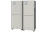
Communication Adaptor (CZ-CFUNC1U)
 |
View all Panasonic WU-192ME2U9 manuals
Add to My Manuals
Save this manual to your list of manuals |
Page 347 highlights
9. Communication Adaptor (CZ-CFUNC1U) Control of 2WAY VRF SYSTEM Instructions for the Electrical Installer For your safety Read the following instructions carefully, and carry out secure installation and electrical work. The precautions given in this manual consist of specific "Warnings" and "Cautions". They provide important safety-related information. Be sure to strictly observe all safety procedures. The labels and their meanings are as described below. Warning Caution This symbol refers to a hazard or unsafe procedure or practice that can result in severe personal injury or death. This symbol refers to a hazard or unsafe procedure or practice that can result in personal injury or product or property damage. * After installation is completed, perform a test run to check for operating trouble. Explain operating procedures to the customer following the central control device Operating Instructions and then request the customer to store this Instructions for the Electrical Installer together with the central control device Operating Instructions. Warning 1 Be sure to arrange installation by the dealer where the system was purchased or by a professional installer. Electric shock or fire may result if an inexperienced person performs any installation or wiring procedures incorrectly. Be sure that this unit is securely installed in accordance with this Instructions for the Electrical Installer. Electric shock or fire may result if any installation or wiring procedures are incorrectly performed. Only a qualified electrician should attempt to connect this system, in accordance with the instructions in this manual. Insufficient electrical circuit capacity or incorrect installation may cause electric shock and fire. Use the specified cables for the electrical connections, and connect the cables securely. Run and fasten the cables securely so that 2 external forces or pressure placed on the cables will not be transmitted to the connection terminals. Overheating or fire may result if connections or attachments are not secure. Depending on the installation conditions and location, an earth leakage breaker may be required. If an earth-leakage breaker is not installed, there is a danger of electric shock or fire. Caution 3 Ground yourself to discharge static electricity before performing any wiring. Note: This equipment has been tested and found to comply with the limits for a Class B digital device, pursuant to part 15 of the FCC Rules. These limits are designed to provide reasonable protection against harmful interference in a residential installation. This equipment generates, uses and can radiate radio frequency energy and, if not installed and used in accordance with the instructions, may cause harmful interference to 4 radio communications. However, there is no guarantee that interference will not occur in a particular installation. If this equipment does cause harmful interference to radio or television reception, which can be determined by turning the equipment off and on, the user is encouraged to try to correct the interference by one or more of the following measures: • Reorient or relocate the receiving antenna. • Increase the separation between the equipment and receiver. • Connect the equipment into an outlet on a circuit different from that to which the receiver is connected. • Consult the dealer or an experienced radio/TV technician for help. 5 1 Installing Note Do not run the indoor/outdoor communication lines, input/ output lines, and power cables through the same conduit, or 6 twist those cables together, or place the cables near one another. It can cause malfunction. Install the main unit away from any sources of electrical noise. Avoid installing in any locations where the unit may come into contact with water, or in any extremely humid locations. Avoid installing in any location that is subject to excessive vibration or physical impacts. 7 (1) After determining the attachment position, secure the installation hardware as shown in the dimensions diagram. If the included screws will not work for the installation, prepare appropriate screws (such as metric ones) for use at the site. (2) Attach the main unit and fasten the installation hardware as illustrated. (3) If the installation hardware is loose or appears like it will fall out, remove the upper case on the unit and secure with screws in the failsafe screw holes. 3 - 275 8 Power supply line Communication lines Input/output lines 9
-
 1
1 -
2
-
3
-
4
-
5
-
6
-
7
-
8
-
9
-
10
-
11
-
12
-
13
-
14
-
15
-
16
-
17
-
18
-
19
-
20
-
21
-
22
-
23
-
24
-
25
-
26
-
27
-
28
-
29
-
30
-
31
-
32
-
33
-
34
-
35
-
36
-
37
-
38
-
39
-
40
-
41
-
42
-
43
-
44
-
45
-
46
-
47
-
48
-
49
-
50
-
51
-
52
-
53
-
54
-
55
-
56
-
57
-
58
-
59
-
60
-
61
-
62
-
63
-
64
-
65
-
66
-
67
-
68
-
69
-
70
-
71
-
72
-
73
-
74
-
75
-
76
-
77
-
78
-
79
-
80
-
81
-
82
-
83
-
84
-
85
-
86
-
87
-
88
-
89
-
90
-
91
-
92
-
93
-
94
-
95
-
96
-
97
-
98
-
99
-
100
-
101
-
102
-
103
-
104
-
105
-
106
-
107
-
108
-
109
-
110
-
111
-
112
-
113
-
114
-
115
-
116
-
117
-
118
-
119
-
120
-
121
-
122
-
123
-
124
-
125
-
126
-
127
-
128
-
129
-
130
-
131
-
132
-
133
-
134
-
135
-
136
-
137
-
138
-
139
-
140
-
141
-
142
-
143
-
144
-
145
-
146
-
147
-
148
-
149
-
150
-
151
-
152
-
153
-
154
-
155
-
156
-
157
-
158
-
159
-
160
-
161
-
162
-
163
-
164
-
165
-
166
-
167
-
168
-
169
-
170
-
171
-
172
-
173
-
174
-
175
-
176
-
177
-
178
-
179
-
180
-
181
-
182
-
183
-
184
-
185
-
186
-
187
-
188
-
189
-
190
-
191
-
192
-
193
-
194
-
195
-
196
-
197
-
198
-
199
-
200
-
201
-
202
-
203
-
204
-
205
-
206
-
207
-
208
-
209
-
210
-
211
-
212
-
213
-
214
-
215
-
216
-
217
-
218
-
219
-
220
-
221
-
222
-
223
-
224
-
225
-
226
-
227
-
228
-
229
-
230
-
231
-
232
-
233
-
234
-
235
-
236
-
237
-
238
-
239
-
240
-
241
-
242
-
243
-
244
-
245
-
246
-
247
-
248
-
249
-
250
-
251
-
252
-
253
-
254
-
255
-
256
-
257
-
258
-
259
-
260
-
261
-
262
-
263
-
264
-
265
-
266
-
267
-
268
-
269
-
270
-
271
-
272
-
273
-
274
-
275
-
276
-
277
-
278
-
279
-
280
-
281
-
282
-
283
-
284
-
285
-
286
-
287
-
288
-
289
-
290
-
291
-
292
-
293
-
294
-
295
-
296
-
297
-
298
-
299
-
300
-
301
-
302
-
303
-
304
-
305
-
306
-
307
-
308
-
309
-
310
-
311
-
312
-
313
-
314
-
315
-
316
-
317
-
318
-
319
-
320
-
321
-
322
-
323
-
324
-
325
-
326
-
327
-
328
-
329
-
330
-
331
-
332
-
333
-
334
-
335
-
336
-
337
-
338
-
339
-
340
-
341
-
 342
342 -
 343
343 -
 344
344 -
 345
345 -
 346
346 -
 347
347 -
 348
348 -
 349
349 -
 350
350 -
 351
351 -
 352
352 -
353
-
354
-
355
-
356
-
357
-
358
-
359
-
360
-
361
-
362
-
363
-
364
-
365
-
366
-
367
-
368
-
369
-
370
-
371
-
372
-
373
-
374
-
375
-
376
-
377
-
378
-
379
-
380
-
381
-
382
-
383
-
384
-
385
-
386
-
387
-
388
-
389
-
390
-
391
-
392
-
393
-
394
-
395
-
396
-
397
-
398
-
399
-
400
-
401
-
402
-
403
-
404
-
405
-
406
-
407
-
408
-
409
-
410
-
411
-
412
-
413
-
414
-
415
-
416
-
417
-
418
-
419
-
420
-
421
-
422
-
423
-
424
-
425
-
426
-
427
-
428
-
429
-
430
-
431
-
432
-
433
-
434
-
435
-
436
-
437
-
438
-
439
-
440
-
441
-
442
-
443
-
444
-
445
-
446
-
447
-
448
-
449
-
450
-
451
-
452
-
453
-
454
-
455
-
456
-
457
-
458
-
459
-
460
-
461
-
462
-
463
-
464
-
465
-
466
-
467
-
468
-
469
-
470
-
471
-
472
-
473
-
474
-
475
-
476
-
477
-
478
-
479
-
480
-
481
-
482
-
483
-
484
-
485
-
486
-
487
-
488
-
489
-
490
-
491
-
492
-
493
-
494
-
495
-
496
-
497
-
498
-
499
-
500
-
501
-
502
-
503
-
504
-
505
-
506
-
507
-
508
-
509
-
510
 |
 |
