Panasonic WU-192ME2U9 Technical Data Manual - Page 237
Fig. 3-26, Installation of Connected Schedule Timers, Wiring the Schedule Timer
 |
View all Panasonic WU-192ME2U9 manuals
Add to My Manuals
Save this manual to your list of manuals |
Page 237 highlights
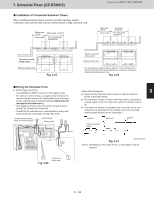
7. Schedule Timer (CZ-ESWC2) ڦInstallation of Connected Schedule Timers When installing schedule timers (remote controller switches, system controllers, etc.) onto the wall, use the method shown in Figs. 3-24 and 3-25. More than 3-3/4" (From wall) More than 4-15/16" (For connected installation) Control of 2WAY VRF SYSTEM More than 3-3/4" (From wall) More than 4-15/16" (For connected installation) Remote controller wiring outlet Electric jinction box Fig. 3-24 ڦWiring the Schedule Timer Before beginning wiring - Use AWG#20 to AWG#14 wires for field supply wiring. - For inter-unit control wiring, use signal wires that allow the remote controller wiring to be differentiated from the power wiring, and take care to prevent miswiring. (Miswiring will damage the schedule timer.) - Use shielded wiring for Inter-unit control wiring and power wiring(T10). (Except North America) - Check that the schedule timer communications wiring and power wiring are connected correctly. (Fig. 3-26) Communications wiring (Inter-unit control wiring) Power wiring Wiring outlet Precautions Do not allow a screwdriver or other metal object to touch the PCB terminals when the power is ON. Communications terminal All switches are OFF when the unit is shipped. : OFF : ON Connected device 1 Inter-unit Remote controller communication (4 wires) Timer group setting 2 3 1Gr 2Gr 3Gr Manual fixed fixed fixed assignment Schedule timer address 5 6 7 12345678 Temp. Opr. Start/ setting mode Stop Remote controller prohibit not used. Power (remote terminal controller terminal) Permitted items for controller operation 1 Permit all modes Permit the below items only Prohibited items for controller operation 2 3 4 Current-time synchronization communication Fig. 3-26 Under-case (back case) Remote controller wiring outlet 1 Electric jinction box * For maintenance reasons, leave a gap of 1" or more between the remote controller switch and schedule timer if they are arranged in parallel above/below each other. Fig. 3-25 2 3 Route the A/C inter-unit control wiring for central control as shown in the figure below. The maximum number of indoor units that can be connected to a single system is 64. The maximum number of outdoor units is 30. The maximum number of schedule timer units that can be con- 4 nected is 8. (A maximum of 10 schedule timer units and other central control devices can be connected.) System 1 System 2 System 3 Inter-unit control wiring 5 1-1 1-2 1-3 2-1 2-2 2-3 3-1 Fig. 3-27 Schedule timer 6 Depending on the model of A/C, a local adapter may be required. 7 8 3 - 165 9
-
 1
1 -
2
-
3
-
4
-
5
-
6
-
7
-
8
-
9
-
10
-
11
-
12
-
13
-
14
-
15
-
16
-
17
-
18
-
19
-
20
-
21
-
22
-
23
-
24
-
25
-
26
-
27
-
28
-
29
-
30
-
31
-
32
-
33
-
34
-
35
-
36
-
37
-
38
-
39
-
40
-
41
-
42
-
43
-
44
-
45
-
46
-
47
-
48
-
49
-
50
-
51
-
52
-
53
-
54
-
55
-
56
-
57
-
58
-
59
-
60
-
61
-
62
-
63
-
64
-
65
-
66
-
67
-
68
-
69
-
70
-
71
-
72
-
73
-
74
-
75
-
76
-
77
-
78
-
79
-
80
-
81
-
82
-
83
-
84
-
85
-
86
-
87
-
88
-
89
-
90
-
91
-
92
-
93
-
94
-
95
-
96
-
97
-
98
-
99
-
100
-
101
-
102
-
103
-
104
-
105
-
106
-
107
-
108
-
109
-
110
-
111
-
112
-
113
-
114
-
115
-
116
-
117
-
118
-
119
-
120
-
121
-
122
-
123
-
124
-
125
-
126
-
127
-
128
-
129
-
130
-
131
-
132
-
133
-
134
-
135
-
136
-
137
-
138
-
139
-
140
-
141
-
142
-
143
-
144
-
145
-
146
-
147
-
148
-
149
-
150
-
151
-
152
-
153
-
154
-
155
-
156
-
157
-
158
-
159
-
160
-
161
-
162
-
163
-
164
-
165
-
166
-
167
-
168
-
169
-
170
-
171
-
172
-
173
-
174
-
175
-
176
-
177
-
178
-
179
-
180
-
181
-
182
-
183
-
184
-
185
-
186
-
187
-
188
-
189
-
190
-
191
-
192
-
193
-
194
-
195
-
196
-
197
-
198
-
199
-
200
-
201
-
202
-
203
-
204
-
205
-
206
-
207
-
208
-
209
-
210
-
211
-
212
-
213
-
214
-
215
-
216
-
217
-
218
-
219
-
220
-
221
-
222
-
223
-
224
-
225
-
226
-
227
-
228
-
229
-
230
-
231
-
 232
232 -
 233
233 -
 234
234 -
 235
235 -
 236
236 -
 237
237 -
 238
238 -
 239
239 -
 240
240 -
 241
241 -
 242
242 -
243
-
244
-
245
-
246
-
247
-
248
-
249
-
250
-
251
-
252
-
253
-
254
-
255
-
256
-
257
-
258
-
259
-
260
-
261
-
262
-
263
-
264
-
265
-
266
-
267
-
268
-
269
-
270
-
271
-
272
-
273
-
274
-
275
-
276
-
277
-
278
-
279
-
280
-
281
-
282
-
283
-
284
-
285
-
286
-
287
-
288
-
289
-
290
-
291
-
292
-
293
-
294
-
295
-
296
-
297
-
298
-
299
-
300
-
301
-
302
-
303
-
304
-
305
-
306
-
307
-
308
-
309
-
310
-
311
-
312
-
313
-
314
-
315
-
316
-
317
-
318
-
319
-
320
-
321
-
322
-
323
-
324
-
325
-
326
-
327
-
328
-
329
-
330
-
331
-
332
-
333
-
334
-
335
-
336
-
337
-
338
-
339
-
340
-
341
-
342
-
343
-
344
-
345
-
346
-
347
-
348
-
349
-
350
-
351
-
352
-
353
-
354
-
355
-
356
-
357
-
358
-
359
-
360
-
361
-
362
-
363
-
364
-
365
-
366
-
367
-
368
-
369
-
370
-
371
-
372
-
373
-
374
-
375
-
376
-
377
-
378
-
379
-
380
-
381
-
382
-
383
-
384
-
385
-
386
-
387
-
388
-
389
-
390
-
391
-
392
-
393
-
394
-
395
-
396
-
397
-
398
-
399
-
400
-
401
-
402
-
403
-
404
-
405
-
406
-
407
-
408
-
409
-
410
-
411
-
412
-
413
-
414
-
415
-
416
-
417
-
418
-
419
-
420
-
421
-
422
-
423
-
424
-
425
-
426
-
427
-
428
-
429
-
430
-
431
-
432
-
433
-
434
-
435
-
436
-
437
-
438
-
439
-
440
-
441
-
442
-
443
-
444
-
445
-
446
-
447
-
448
-
449
-
450
-
451
-
452
-
453
-
454
-
455
-
456
-
457
-
458
-
459
-
460
-
461
-
462
-
463
-
464
-
465
-
466
-
467
-
468
-
469
-
470
-
471
-
472
-
473
-
474
-
475
-
476
-
477
-
478
-
479
-
480
-
481
-
482
-
483
-
484
-
485
-
486
-
487
-
488
-
489
-
490
-
491
-
492
-
493
-
494
-
495
-
496
-
497
-
498
-
499
-
500
-
501
-
502
-
503
-
504
-
505
-
506
-
507
-
508
-
509
-
510
 |
 |
