2011 Kawasaki KX250F Owners Manual
2011 Kawasaki KX250F Manual

2011 Kawasaki KX250F manual content summary:
- 2011 Kawasaki KX250F | Owners Manual - Page 1
- 2011 Kawasaki KX250F | Owners Manual - Page 2
- 2011 Kawasaki KX250F | Owners Manual - Page 3
Quick Reference Guide This Quick Reference Guide will assist you in finding the information you're looking for. GENERAL INFORMATION MAINTENANCE AND ADJUSTMENT TROUBLESHOOTING GUIDE TUNING STORAGE A Table of Contents is included after the Foreword. - 2011 Kawasaki KX250F | Owners Manual - Page 4
limited to participation in sanctioned competition events upon a closed • The course. vehicle should not be used for general off-road recreational riding. • This • Read owner's manual. - 2011 Kawasaki KX250F | Owners Manual - Page 5
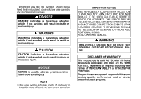
shown below, heed their instructions! Always follow safe FOR GENERAL OFF-ROAD RECREATIONAL RIDING. READ OWNER'S MANUAL. DANGER DANGER indicates a hazardous situation which, if all responsibilities concerning quality, performance, cost of service and/or necessary repairs. CAUTION CAUTION indicates - 2011 Kawasaki KX250F | Owners Manual - Page 6
conducted, this sport has the potential to cause environmental problems as well as conflicts with other people. Responsible use of your off-road motorcycle will ensure that these problems and conflicts do not occur. TO PROTECT THE FUTURE OF YOUR - 2011 Kawasaki KX250F | Owners Manual - Page 7
tuned competition machine for participation in racing events. As with any mechanical device, proper care and maintenance are important for trouble-free operation and top performance. This manual is written to enable you to keep your KX properly tuned and adjusted. Due to improvements in design and - 2011 Kawasaki KX250F | Owners Manual - Page 8
Inspection ...145 Tightening Torques of Nuts and Bolts ...146 Cleaning Your Motorcycle ...151 Lubrication ...153 DFI Self-Diagnosis ...156 TROUBLESHOOTING GUIDE ...161 TUNING ...168 Suspension ...168 Gearing ...174 Special Care According to Track Conditions ...175 OPTIONAL PARTS ...176 PRE-RACE - 2011 Kawasaki KX250F | Owners Manual - Page 9
SPECIFICATIONS 7 SPECIFICATIONS DIMENSIONS Overall Length Overall Width Overall Height Wheelbase Road Clearance Curb Mass Fuel Tank Capacity ENGINE Type Bore × Stroke Displacement Compression Ratio Fuel System Starting System Ignition System Ignition Timing Lubrication System Spark Plug Spark Plug - 2011 Kawasaki KX250F | Owners Manual - Page 10
8 SPECIFICATIONS Clutch Type Driving System Gear Ratio: 1st 2nd 3rd 4th 5th Primary Reduction Ratio Final Reduction Ratio Overall Drive Ratio Engine Oil: Type Viscosity Capacity FRAME Type Steering Angle Caster Trail Tire Size/Type: Front Rear Wet, multi disc Chain drive 2.142 (30/14) 1.750 (28/16) - 2011 Kawasaki KX250F | Owners Manual - Page 11
SPECIFICATIONS 9 Rim Size: Front Rear Suspension: Front Rear Front Suspension Travel Rear Wheel Travel Front Fork Oil: Type Capacity (Left Front Fork): Cylinder Unit Outer Tube Capacity (Right Front Fork) BRAKES Type: Front Rear Single disc Single disc SHOWA SS19 260 mL (8.79 US oz.) 357 mL (12.1 US - 2011 Kawasaki KX250F | Owners Manual - Page 12
10 GENERAL INFORMATION GENERAL INFORMATION Location of Parts 1. Clutch Lever 2. Engine Stop Button 3. Fuel Tank Cap 4. Front Brake Fluid Reservoir 5. Front Brake Lever 6. Throttle Grip - 2011 Kawasaki KX250F | Owners Manual - Page 13
GENERAL INFORMATION 11 1. Front Fork 2. Radiator 3. Fuel Tank 4. Throttle Body Assy 5. Seat 6. Air Cleaner Element 7. Brake Disc 8. Brake Caliper 9. Shift Pedal 10. Rear Shock Absorber 11. Swingarm 12. Drive Chain 13. Chain Guide - 2011 Kawasaki KX250F | Owners Manual - Page 14
12 GENERAL INFORMATION 1. Muffler 2. Rear Brake Fluid Reservoir 3. Rear Shock Absorber Gas Reservoir 4. Kick Pedal 5. Uni-Trak® Tie-Rod and Rocker Arm 6. Oil Level Gauge 7. Rear Brake Pedal 8. Exhaust Pipe - 2011 Kawasaki KX250F | Owners Manual - Page 15
in injury. Do not start the engine or attempt to ride the motorcycle when the side stand is installed. A. Fuel Tank Cap B. Breather Hose NOTE ○ Support the motorcycle with a suitable stand to perform maintenance or adjustment procedures. - 2011 Kawasaki KX250F | Owners Manual - Page 16
standard industry specifications may result in unsatisfactory performance. Operating problems that result from the use of poor quality or nonrecommended with a minimum Antiknock Index of 90. The Antiknock Index is posted on service station pumps in the U.S.A. The octane rating of a gasoline is a - 2011 Kawasaki KX250F | Owners Manual - Page 17
containing more than 5% methanol. Fuel system damage and performance problems may result. Gasoline/Ether Blends - The most common ether is you drain all fuel from the fuel system. See the Storage section in this manual. NOTE ○ Other oxygenates approved for use in unleaded gasoline include TAME (up - 2011 Kawasaki KX250F | Owners Manual - Page 18
16 GENERAL INFORMATION Kick Pedal This motorcycle is equipped with a primary kick starting system. When the clutch lever is pulled, the motorcycle can be started with the transmission in any gear. Starting the Engine • Shift the transmission into neutral. WARNING Riding with the side stand can - 2011 Kawasaki KX250F | Owners Manual - Page 19
GENERAL INFORMATION 17 • When engine is cold Pull out the idle adjusting screw/choke knob. • When engine is already warm or restarts Kick the engine over, leaving the throttle closed without using the idle adjusting screw/choke knob. NOTE ○ If the engine fails starting, open the throttle fully - 2011 Kawasaki KX250F | Owners Manual - Page 20
18 GENERAL INFORMATION Shifting Gears This motorcycle is equipped with a 5-speed "return shift" transmission. The neutral is located halfway between 1st and 2nd gear. "Return shift" means that when shifting up or down, each gear must be engaged before the next higher or lower gear may be selected. - 2011 Kawasaki KX250F | Owners Manual - Page 21
GENERAL INFORMATION 19 Stopping the Motorcycle For maximum deceleration, close the throttle and apply both front and rear brakes. Pull in the clutch lever as the motorcycle comes to a stop. Independent use of the front or rear brake may be advantageous in certain circumstances. Shift down - 2011 Kawasaki KX250F | Owners Manual - Page 22
in the engine and transmission, which are necessary for performance and reliability. techniques and avoiding recklessly high engine speeds will keep the engine trouble-free. NOTICE When any following parts have been replaced, the same break-in procedure as the new motorcycle must be carried out - 2011 Kawasaki KX250F | Owners Manual - Page 23
GENERAL INFORMATION 21 Daily Pre-Ride Checks Check the following items each day before you ride. The time required is minimal, and habitual performance of these checks will help ensure a safe, reliable ride. If any irregularities are found during these checks, refer to the appropriate section and - 2011 Kawasaki KX250F | Owners Manual - Page 24
22 GENERAL INFORMATION Engine Sprocket ...Frame Tires ...No wear or damage Overall condition good No wear or damage Pressure correct Air valve cap installed No looseness Overall condition good Chain slack correct Oil if necessary Function properly Lever and pedal play correct No fluid leakage - 2011 Kawasaki KX250F | Owners Manual - Page 25
GENERAL INFORMATION 23 After-Race Checks After racing, first clean the motorcycle, then inspect the entire motorcycle with special attention to the air cleaner, brakes, etc. Carry out the general lubrication and make necessary adjustments. - 2011 Kawasaki KX250F | Owners Manual - Page 26
24 MAINTENANCE AND ADJUSTMENT MAINTENANCE AND ADJUSTMENT Periodic Maintenance Chart The maintenance and adjustments outlined in this chapter are easily carried out and must be done in accordance with the Periodic Maintenance Chart to keep the motorcycle in good running condition. 1. Periodic - 2011 Kawasaki KX250F | Owners Manual - Page 27
MAINTENANCE AND ADJUSTMENT 25 FREQUENCY After each Every 3 Every 6 Every 12 race (or 2.5 races (or races (or 15 races (or hour) 7.5 hour) hour) 30 hour) As required See Page 34 OPERATION Water hoses and connections - inspect † • - 2011 Kawasaki KX250F | Owners Manual - Page 28
26 MAINTENANCE AND ADJUSTMENT 2. Periodic Inspection (Chassis Related Item) FREQUENCY After each Every 3 race (or 2.5 races (or hour) 7.5 hour) Every 6 Every 12 races (or 15 races (or hour) 30 hour) As required See Page 87 91 88 142 79 85 82 94 146 OPERATION Brake - adjust † Brake pad wear - - 2011 Kawasaki KX250F | Owners Manual - Page 29
MAINTENANCE AND ADJUSTMENT 27 FREQUENCY After each Every 3 race (or 2.5 races (or hour) 7.5 hour) Every 6 Every 12 races (or 15 races (or hour) 30 hour) As required See Page - - 142 136 - OPERATION Swingarm and UNI-TRAK linkage pivK ots - lubricate Frame - inspect Wheels/tires - inspect Rear shock - 2011 Kawasaki KX250F | Owners Manual - Page 30
2 years Every 2 years Every 4 years 30 30 - • - 75 39 - - - - 100 - - K Brake hoses - replace • Every 4 years • †: Replace, add, adjust, clean or torque if necessary. K: Should be serviced by referring to the Service Manual or an authorized Kawasaki dealer. - 2011 Kawasaki KX250F | Owners Manual - Page 31
seizure, accident, and injury. Check the oil level before each ride and change the oil according to the periodic maintenance chart in the Owner 's Manual. Because of the semi-dry sump lubrication system, the engine oil level indicated on the oil level gauge will fluctuate depending on the motorcycle - 2011 Kawasaki KX250F | Owners Manual - Page 32
30 MAINTENANCE AND ADJUSTMENT NOTE ○ If no oil appears in the oil level gauge, tip the mo- torcycle slightly to the right until oil is visible then return to an upright position. If no oil appears even when tipped at an extreme angle, remove the drain bolt to empty any oil that may be in the - 2011 Kawasaki KX250F | Owners Manual - Page 33
MAINTENANCE AND ADJUSTMENT 31 the oil filter is replaced, remove the oil filter • When cap bolts and take off the cap with O-ring and spring. A. Oil Filter Element B. Grommet A. Oil Filter Cap B. Bolts the oil filter element with a new one. • Replace Apply grease the grommet. • Install the oil to - 2011 Kawasaki KX250F | Owners Manual - Page 34
40 *Kawasaki Performance Oils and Lubricants have been specifically engineered for your vehicle. Consistent use of these products meets or exceeds warranty and service requirements and can help to extend the life of your Kawasaki. Engine Oil Capacity Capacity: 0.75 L (0.79 US qt) (When filter is not - 2011 Kawasaki KX250F | Owners Manual - Page 35
MAINTENANCE AND ADJUSTMENT 33 Type: API SG, SH, SJ, SL or SM with JASO MA, MA1 or MA2 Viscosity: SAE 10W-30, 10W-40, 10W-50 Tightening Torque Oil Filler Plug: 5.0 N·m (0.51 kgf·m, 44 in·lb) the engine. • Start Check the oil level and oil leakage. • NOTE ○ Do not add any chemical additive to the - 2011 Kawasaki KX250F | Owners Manual - Page 36
34 MAINTENANCE AND ADJUSTMENT Cooling System Water Hoses Check the water hoses for cracks or deterioration, and the connections for looseness in accordance with the Periodic Maintenance Chart. WARNING The cooling system can get extremely hot during normal operation and cause serious burns. Do not - 2011 Kawasaki KX250F | Owners Manual - Page 37
MAINTENANCE AND ADJUSTMENT 35 • Remove the bolts and right radiator shroud. Coolant Level Inspection A. Radiator Cap A. Bolts B. Right Radiator Shroud the coolant level in the radiator. The cool• Check ant should come up to the bottom of the radiator filler neck. the motorcycle perpendicular to - 2011 Kawasaki KX250F | Owners Manual - Page 38
36 MAINTENANCE AND ADJUSTMENT • Tighten the bolts. Tightening Torque Radiator Shroud Bolts: 9.8 N·m (1.0 kgf·m, 87 in·lb) Coolant Change A. Coolant Level B. Filler Neck the coolant level is low, add coolant through the • If radiator filler opening to the bottom of the filler neck. Water and - 2011 Kawasaki KX250F | Owners Manual - Page 39
MAINTENANCE AND ADJUSTMENT 37 whitish cotton-like wafts are observed, alumi• If num parts in the cooling system are corroded and the coolant is brown, iron or steel parts are rust• If ing and the system must be flushed. the cooling system for damage, loose con• Check nections, and leaks. the coolant - 2011 Kawasaki KX250F | Owners Manual - Page 40
38 MAINTENANCE AND ADJUSTMENT NOTICE Use coolant containing corrosion inhibitors made specifically for aluminum engines and radiators in accordance with the instruction of the manufacture. Soft or distilled water must be used with the antifreeze in the cooling system. If hard water is used in the - 2011 Kawasaki KX250F | Owners Manual - Page 41
MAINTENANCE AND ADJUSTMENT 39 brush or other suitable tool. If the spark plug electrodes are corroded, or damaged, or if the insulator is cracked, replace the plug. The standard spark plug is shown in the table below. Standard Spark Plug NGK CPR8EB-9 To find out whether the plug's heat range is - 2011 Kawasaki KX250F | Owners Manual - Page 42
40 MAINTENANCE AND ADJUSTMENT • Remove the fuel tank mounting bolt and band. sure to place a piece of cloth around the fuel • Be hose joint. a thin blade screwdriver into the slit on the • Insert joint lock. A. Fuel Tank Mounting Bolt B. Band A. Cloth B. Thin Blade Screwdriver C. Joint Lock - 2011 Kawasaki KX250F | Owners Manual - Page 43
MAINTENANCE AND ADJUSTMENT 41 the driver to disconnect the joint lock. • Turn Pull the fuel hose joint out of the outlet pipe. • the fuel pump lead connector. • Disconnect Remove the fuel tank. • A. Turn B. Joint Lock C. Fuel Hose Joint A. Fuel Pump Lead Connector WARNING Gasoline is extremely - 2011 Kawasaki KX250F | Owners Manual - Page 44
42 MAINTENANCE AND ADJUSTMENT the cylinder head cover around the spark • Clean plug cap hole before removing the spark plug. the spark plug cap off the plug before remov• Pull ing the spark plug. the spark plug cap as shown in the figure. • Install Pull up the plug cap lightly to make sure of the in - 2011 Kawasaki KX250F | Owners Manual - Page 45
MAINTENANCE AND ADJUSTMENT 43 the fuel hose joint straight onto the fuel out• Insert let pipe until the hose joint clicks. • Push the joint lock until the hose joint clicks. and pull the fuel hose joint back and forth • Push more than two times, and make sure it is locked and does not come off. A. - 2011 Kawasaki KX250F | Owners Manual - Page 46
44 MAINTENANCE AND ADJUSTMENT NOTE ○ To prevent the bottom of the fuel tank from push- ing the throttle cables, run the throttle cables over the black connector correctly. A. Throttle Cables B. Fuel Tank C. Bottom of the Frame (Right Side) • Install the removed parts. A. Throttle Cables B. - 2011 Kawasaki KX250F | Owners Manual - Page 47
MAINTENANCE AND ADJUSTMENT 45 Air Cleaner A clogged air cleaner restricts the air intake, increases fuel consumption, reduces engine power, and can cause spark plug fouling. Inspect the air intake system, which includes the air filter and air duct to the throttle body assy, and the duct clamps and - 2011 Kawasaki KX250F | Owners Manual - Page 48
46 MAINTENANCE AND ADJUSTMENT the both side covers slightly outward and • Open slide the seat backward. the wing bolt, and take out the air cleaner • Remove element. A. Side Covers B. Seat A. Air Cleaner Element B. Wing Bolt inside of the intake tract and throttle body • Check assy for dirt. If - 2011 Kawasaki KX250F | Owners Manual - Page 49
MAINTENANCE AND ADJUSTMENT 47 the element. If it is dirty, clean it. Also • Inspect check if the element is in good condition (no tears, hardening or shrinkage). If damaged, replace the element or it will allow dirt into the throttle body assy. WARNING A clogged air cleaner may allow dirt and dust - 2011 Kawasaki KX250F | Owners Manual - Page 50
48 MAINTENANCE AND ADJUSTMENT WARNING Gasoline and low-flash point solvents can be flammable and/or explosive and cause severe burns. Clean the element in a well-ventilated area, and take care that there is no spark or flame anywhere near the working areas. Do not use gasoline or low-flash point - 2011 Kawasaki KX250F | Owners Manual - Page 51
MAINTENANCE AND ADJUSTMENT 49 the air cleaner element so that its tab faces • Install upward and its projections align with the holes in the housing. A. Apply grease. A. Tab B. Projections C. Holes - 2011 Kawasaki KX250F | Owners Manual - Page 52
50 MAINTENANCE AND ADJUSTMENT the hooks of the seat under the flange collar • Insert and brackets. the tabs of the side covers into the inside of • Install the seat, and tighten the bolts. A. Hooks B. Seat C. Flange Collar D. Brackets A. Tabs B. Seat up the rear end of the seat to make sure it is - 2011 Kawasaki KX250F | Owners Manual - Page 53
MAINTENANCE AND ADJUSTMENT 51 Throttle Cable Throttle Cable Adjustment Inspect the throttle grip for smooth operation in all steering positions. Check and adjust the throttle cable in accordance with the Periodic Maintenance Chart. Check that the throttle grip has 2 ~ 3 mm (0.08 ~ 0.12 in.) of play - 2011 Kawasaki KX250F | Owners Manual - Page 54
52 MAINTENANCE AND ADJUSTMENT Throttle Body Assy warm up the engine. • Thoroughly Turn the idle adjusting screw/choke knob to adjust • the idle speed 2 000 ~ 2 100 r/min (rpm) by using the engine revolution tester (The tester should be followed by the method described by the manufacture.). Idle - 2011 Kawasaki KX250F | Owners Manual - Page 55
MAINTENANCE AND ADJUSTMENT 53 the bolt and take off the side cover on • Remove both sides. the muffler clamp bolt. • Loosen Remove the muffler mounting bolts, and pull out • the muffler body backward. A. Bolt B. Side Cover A. Muffler Clamp Bolt B. Muffler Mounting Bolts C. Muffler Body - 2011 Kawasaki KX250F | Owners Manual - Page 56
54 MAINTENANCE AND ADJUSTMENT • Loosen the air cleaner duct clamp screw. the intake air temperature sensor con• Disconnect nector. A. Air Cleaner Duct Clamp Screw A. Intake Air Temperature Sensor Connector - 2011 Kawasaki KX250F | Owners Manual - Page 57
MAINTENANCE AND ADJUSTMENT 55 the rear frame mounting bolts on the left • Remove and right sides. the rear frame backward with the air cleaner • Pull housing. • Disconnect the throttle sensor connector. A. Throttle Sensor Connector A. Rear Frame Mounting Bolts B. Air Cleaner Housing - 2011 Kawasaki KX250F | Owners Manual - Page 58
56 MAINTENANCE AND ADJUSTMENT the intake air pressure sensor con• Disconnect nector. • Disconnect the fuel injector connector. sure to place a piece of cloth around the fuel • Be hose joint. a thin blade screwdriver into the slit on the • Insert joint lock. A. Intake Air Pressure Sensor Connector - 2011 Kawasaki KX250F | Owners Manual - Page 59
MAINTENANCE AND ADJUSTMENT 57 the driver to disconnect the joint lock. • Turn Pull the fuel hose joint out of the delivery pipe. • • Free the main harness from the clamps. A. Turn B. Joint Lock C. Fuel Hose Joint A. Main Harness B. Clamps - 2011 Kawasaki KX250F | Owners Manual - Page 60
58 MAINTENANCE AND ADJUSTMENT the throttle body assy holder clamp screw. • Loosen Pull the throttle body assy from the holder. • the bolts and clamps, and take off the • Remove throttle pulley cover. A. Throttle Body Assy Holder Clamp Screw A. Throttle Pulley Cover Bolts B. Throttle Pulley Cover - 2011 Kawasaki KX250F | Owners Manual - Page 61
MAINTENANCE AND ADJUSTMENT 59 the throttle cable bolts, and free the tips of • Loosen throttle cable lower end. the lower ends of the throttle cables and • Lubricate reinstall them in reverse order of removal. Tightening Torque Throttle Cable Bolts: 3.5 N·m (0.36 kgf·m, 31 in·lb) Throttle Pulley - 2011 Kawasaki KX250F | Owners Manual - Page 62
60 MAINTENANCE AND ADJUSTMENT the throttle body assy to the throttle body • Install assy holder. Align the projection with the groove. • Check the throttle body assy is installed securely. • Hold the main harness to the clamps. A. Main Harness B. Clamps A. Groove B. Projection - 2011 Kawasaki KX250F | Owners Manual - Page 63
MAINTENANCE AND ADJUSTMENT 61 the fuel hose joint straight onto the delivery • Insert pipe. the yellow paint of the hose in the throttle • Check body assy side. • Push the joint lock until the hose joint clicks. and pull the fuel hose joint back and forth • Push more than two times, and make sure it - 2011 Kawasaki KX250F | Owners Manual - Page 64
62 MAINTENANCE AND ADJUSTMENT the intake air pressure sensor connector, • Connect fuel injector connector and throttle sensor connecTightening Torque Rear Frame Mounting Bolts: 34 N·m (3.5 kgf·m, 25 ft·lb) the removed parts. • Install Open and close the throttle a few times to make • sure the grip - 2011 Kawasaki KX250F | Owners Manual - Page 65
MAINTENANCE AND ADJUSTMENT 63 Clutch Clutch Lever Adjustment Proper clutch lever free play is 8 ~ 13 mm (0.3 ~ 0.5 in.). Lever play increases with cable stretch and friction plate wear, requiring periodic adjustment. When the clutch lever free play is out of specification, first try adjusting it at - 2011 Kawasaki KX250F | Owners Manual - Page 66
64 MAINTENANCE AND ADJUSTMENT WARNING Too much cable play can prevent clutch disengagement and cause an accident resulting in serious injury or death. When adjusting the clutch or replacing the cable, be sure the upper end of the clutch outer cable is fully seated in its fitting, or it could slip - 2011 Kawasaki KX250F | Owners Manual - Page 67
MAINTENANCE AND ADJUSTMENT 65 • Remove the clutch cover bolts. the clutch cover and gasket. • Remove Remove clutch spring bolts, clutch pressure • plate and the springs. A. Bolts B. Clutch Cover A. Clutch Spring Bolts B. Clutch Pressure Plate - 2011 Kawasaki KX250F | Owners Manual - Page 68
thickness of the friction and steel • Measure plates with vernier calipers. they have worn past the service limit, replace • If them with new ones. Friction Plate Thickness Measurement Standard Service Limit 2.72 ~ 2.88 mm (0.107 ~ 0.113 in.) 2.5 mm (0.10 in.) Friction and Steel Plates Wear/Damage - 2011 Kawasaki KX250F | Owners Manual - Page 69
Friction and Steel Plate Warp Friction Plate Standard 0.15 mm (0.0059 in.) or less 0.15 mm (0.0059 in.) or less Service Limit 0.3 mm (0.012 in.) Steel Plate Standard Service Limit 0.3 mm (0.012 in.) A. Friction and Steel Plates NOTICE If dry steel plates and friction plates are installed, apply - 2011 Kawasaki KX250F | Owners Manual - Page 70
68 MAINTENANCE AND ADJUSTMENT molybdenum disulfide grease to the steel • Apply ball and the contact area of the push rod holder. • Install the steel ball and the push rod holder. A. Apply molybdenum disulfide grease. B. Push Rod Holder C. Steel Ball A. Release Shaft Lever B. Push forward. C. - 2011 Kawasaki KX250F | Owners Manual - Page 71
MAINTENANCE AND ADJUSTMENT 69 Release Shaft Lever Position and Adjusting Washer Selection Position Distance 49.2 ~ 56.5 mm (1.94 ~ 2.22 in.) More than 56.5 mm (2.22 in.) Less than 49.2 mm (1.94 in.) Judgment Standard Too big Too small Washers QuantiThickness ty 1.5 mm (0.06 in.) 1.0 mm (0.04 in.) - 2011 Kawasaki KX250F | Owners Manual - Page 72
70 MAINTENANCE AND ADJUSTMENT Valve Clearance Valve and valve seat wear decreases valve clearance, upsetting valve timing. the cylinder head cover bolts and cylin• Remove der head cover. NOTICE If valve clearance is left unadjusted, wear will eventually cause the valves to remain partly open, - 2011 Kawasaki KX250F | Owners Manual - Page 73
MAINTENANCE AND ADJUSTMENT 71 the head cover gasket and spark plug • Remove hole gasket. • Remove the two caps from the magneto cover. A. Head Cover Gasket B. Spark Plug Hole Gasket A. Timing Inspection Cap B. Flywheel Nut Cap - 2011 Kawasaki KX250F | Owners Manual - Page 74
72 MAINTENANCE AND ADJUSTMENT the piston to the Top Dead Center (TDC) of • Bring its compression stroke to inspect the valve clearance (the position at the end of the compression stroke) by aligning the top mark with the groove on the magneto cover while turning the crankshaft counterclockwise. this - 2011 Kawasaki KX250F | Owners Manual - Page 75
clearance. • • If the valve clearance is not within the specified range, adjust by an authorized Kawasaki dealer or a competent mechanic following the instructions in the Service Manual. Apply silicone sealant to the cylinder head as shown in the figure. A. Thickness Gauge A. Silicone Sealant - 2011 Kawasaki KX250F | Owners Manual - Page 76
cover gasket on the cylinder the spark plug hole gasket with a new • Replace one, and install it. sure that the upper chain guide is bottomed • Make to the cylinder head cover. A. Upper Chain Guide B. Cylinder Head Cover A. Head Cover Gasket B. Spark Plug Hole Gasket NOTICE Unless the upper chain - 2011 Kawasaki KX250F | Owners Manual - Page 77
MAINTENANCE AND ADJUSTMENT 75 Tightening Torque Cylinder Head Cover Bolts: 9.8 N·m (1.0 kgf·m, 87 in·lb) Exhaust System The exhaust system, in particular the muffler body, is designed to reduce exhaust noise and conduct the exhaust gases away from the rider while minimizing power loss. If carbon - 2011 Kawasaki KX250F | Owners Manual - Page 78
76 MAINTENANCE AND ADJUSTMENT the muffler body cover bolts. • Remove Remove the muffler mounting bolt. • the muffler body cover with the plastic • Remove mallet. A. Muffler Body Cover Bolts B. Muffler Mounting Bolt A. Plastic Mallet B. Muffler Body Cover - 2011 Kawasaki KX250F | Owners Manual - Page 79
MAINTENANCE AND ADJUSTMENT 77 the muffler baffle with a new one. • Replace Remove silicone sealant attaching on the muf• fler body the cover and muffler body. the shape of the muffler baffle and install • Arrange the muffler body cover to the muffler body. that the exhaust port of the muffler body • - 2011 Kawasaki KX250F | Owners Manual - Page 80
78 MAINTENANCE AND ADJUSTMENT A. Muffler Body Cover B. Muffler Body C. Muffler Body Cover Bolts D. Silicone Sealant A. Muffler Clamp Bolt B. Muffler Mounting Bolt C. Muffler Body Tightening Torque NOTE ○ If the threaded holes of the muffler body cover and muffler body do not align, remove the - 2011 Kawasaki KX250F | Owners Manual - Page 81
MAINTENANCE AND ADJUSTMENT 79 the tabs of the side cover into the slots of • Insert the air cleaner housing, and tighten the bolts. Drive Chain For safety and to prevent excessive wear, the drive chain must be checked, adjusted, and lubricated before riding. If the chain becomes badly worn or - 2011 Kawasaki KX250F | Owners Manual - Page 82
80 MAINTENANCE AND ADJUSTMENT the same swingarm mark that the notch of the right chain adjuster aligns with. Drive Chain Slack 52 ~ 58 mm (2.0 ~ 2.3 in.) A. Chain Slack addition to checking the slack, rotate the rear • In wheel to inspect the drive chain for damaged roll- • ers, loose pins and - 2011 Kawasaki KX250F | Owners Manual - Page 83
MAINTENANCE AND ADJUSTMENT 81 WARNING Misalignment of the wheel will result in abnormal wear, and may result in an unsafe riding condition. Align the rear wheel using the marks on the swingarm or measuring the distance between the center of the axle and swingarm pivot. both chain adjuster locknuts. - 2011 Kawasaki KX250F | Owners Manual - Page 84
on a straight part of the chain from the center of the 1st pin to the center of the 21st pin. If the length exceeds the service limit, the chain should be replaced. Since overworn sprockets will cause a new chain to wear faster, inspect both the engine and rear sprockets whenever the - 2011 Kawasaki KX250F | Owners Manual - Page 85
B. Tape Measure A. Master Link Clip B. Direction of Chain Rotation Drive Chain 20-Link Length Standard 317.5 ~ 318.2 mm (12.50 ~ 12.53 in.) Service Limit 323 mm (12.7 in.) NOTE ○ The drive system was designed for use with a DAIDO DID 520DMA4 114-links chain. For maximum stretch resistance and - 2011 Kawasaki KX250F | Owners Manual - Page 86
Inspection Visually inspect the drive chain guide and replace it if excessively worn or damaged. inspect the upper and lower of the chain • Visually slipper on the swingarm and replace them if worn or damaged. Chain Slipper Wear Inspection A. Chain Guide A. Upper and Lower of the Chain Slipper - 2011 Kawasaki KX250F | Owners Manual - Page 87
MAINTENANCE AND ADJUSTMENT 85 • Sprocket Wear Inspection Visually inspect the sprocket teeth and replace the sprocket if its teeth are worn or damaged. Sprocket Teeth Wear Chain Lubrication Lubrication of the drive chain is necessary after riding in the rain or mud, or any time the chain appears - 2011 Kawasaki KX250F | Owners Manual - Page 88
86 MAINTENANCE AND ADJUSTMENT Handlebar To suit various riding positions, the handlebar can be adjusted by turning the handlebar holders around. Remove the handlebar pad. Check the handlebar for bent or crack. Remove the handlebar clamp bolts, the clamps and the handlebar. • • • A. Handlebar - 2011 Kawasaki KX250F | Owners Manual - Page 89
There are no parts on the brakes that require adjustment except brake lever position. Brake Lever Position • A. Handlebar Clamps B. Clamp Bolts C. Gap D. Supporting Bar • The brake lever position can be adjusted to suit the rider's preference. To adjust the brake lever position, slide the front - 2011 Kawasaki KX250F | Owners Manual - Page 90
88 MAINTENANCE AND ADJUSTMENT the braking power and check that there is no • Test brake drag. NOTICE Do not spill brake fluid onto any painted surface. Do not use fluid from a container that has been left open or that has been unsealed for a long time. Check for fluid leakage around the brake - 2011 Kawasaki KX250F | Owners Manual - Page 91
MAINTENANCE AND ADJUSTMENT 89 A. Front Brake Reservoir B. Lower Level Line A. Rear Brake Reservoir B. Lower Level Line the brake fluid in the front or rear brake reservoir • If is below the lower level line, check for fluid leaks in the brake line and fill the reservoir to the upper level line ( - 2011 Kawasaki KX250F | Owners Manual - Page 92
90 MAINTENANCE AND ADJUSTMENT A. Front Brake Reservoir B. Upper Level Line A. Rear Brake Reservoir B. Upper Level Line WARNING Mixing brands and types of brake fluid can reduce the brake system's effectiveness and cause an accident resulting in injury or death. Do not mix two brands of brake - 2011 Kawasaki KX250F | Owners Manual - Page 93
MAINTENANCE AND ADJUSTMENT 91 Brake Pad Wear Inspection Inspect the brake pads for wear in accordance with the Periodic Maintenance Chart. If the thickness of any pad in any (front or rear) brake caliper is less than 1 mm (0.04 in.), have both pads in the caliper replaced as a set. Pad replacement - 2011 Kawasaki KX250F | Owners Manual - Page 94
92 MAINTENANCE AND ADJUSTMENT the front wheel off the ground using a jack • Raise (special tool: 57001-1238) and attachment (spethe clamp of the number plate. • Unlock Remove bolt. • Clear thethe holes and remove the number plate. • cial tool: 57001-1252 or 1608). Steering Adjustment A. Push and - 2011 Kawasaki KX250F | Owners Manual - Page 95
MAINTENANCE AND ADJUSTMENT 93 the handlebar (see Handlebar section). • Remove Loosen the • (upper). left and right front fork clamp bolts the steering stem head nut, and raise the • Remove steering stem head. the steering stem locknut with a stem nut • Turn wrench (special tool: 57001-1100) to - 2011 Kawasaki KX250F | Owners Manual - Page 96
proper brake effect, or no brake drag. Install the removed parts. Front Suspension the brake lever, pump the front fork back • Holding and forth manually to check for smooth operation. inspect the front fork for oil leakage, scor• Visually ing or scratches on the outer surface of the inner Front - 2011 Kawasaki KX250F | Owners Manual - Page 97
MAINTENANCE AND ADJUSTMENT 95 Front Fork Adjustment Any of the following front fork adjustments should be made to tune the front suspension to the rider's weight and the condition of the track. Basically, there are seven adjustments you can make to the front fork. Air Pressure Air pressure acts as - 2011 Kawasaki KX250F | Owners Manual - Page 98
96 MAINTENANCE AND ADJUSTMENT NOTICE The right and left fork tubes must be adjusted evenly. Air Pressure Adjustment The standard air pressure in the front fork legs is atmospheric (0 kPa, 0 kgf/cm², 0 psi). Air pressure in the fork legs increase with normal use, so the fork action stiffens during - 2011 Kawasaki KX250F | Owners Manual - Page 99
MAINTENANCE AND ADJUSTMENT 97 A. Screw B. Front Fork Top Plug C. Front Fork (Right Side) A. Rebound Damping Adjuster B. Left Front Fork Cylinder Valve the bottom of the left fork tube. • Clean To adjust rebound damping, turn the adjuster • on the leftthe front fork cylinder valve with a flat-head - 2011 Kawasaki KX250F | Owners Manual - Page 100
98 MAINTENANCE AND ADJUSTMENT Rebound Damping Adjuster Settings compression damping to suit your preference under certain conditions. NOTICE Do not force the compression damping adjuster beyond the fully seated position, or the adjusting mechanism may be damaged. A. Seated Position (Adjuster - 2011 Kawasaki KX250F | Owners Manual - Page 101
MAINTENANCE AND ADJUSTMENT 99 Compression Damping Adjuster Settings the spring preload to suit your preference under certain conditions. NOTICE Do not force the spring preload adjuster beyond the fully seated position, or the adjusting mechanism may be damaged. A. Seated Position (Adjuster Turned - 2011 Kawasaki KX250F | Owners Manual - Page 102
100 MAINTENANCE AND ADJUSTMENT Spring Preload Adjuster Settings NOTICE Be careful not to scratch the inner tube and not to damage the dust seal. Avoid scratching or damaging the inner tube or the dust seal. Use a mild detergent and sponge out dirt with plenty of water. NOTE ○ Set the rebound and - 2011 Kawasaki KX250F | Owners Manual - Page 103
AND ADJUSTMENT 101 A. Front Fork Clamp Bolts (Upper) B. Top Plug Wrench (Special Tool: 57001-1645) the motorcycle using a jack (special tool: • Support 57001-1238) and attachment (special tool: 57001the front axle nut, and then loosen the • Unscrew left front axle clamp bolts. the brake caliper - 2011 Kawasaki KX250F | Owners Manual - Page 104
102 MAINTENANCE AND ADJUSTMENT A. Right Front Axle Clamp Bolts (Loosen) B. Front Axle C. Collar D. Cap A. Front Fork Clamp Bolts (Lower) B. Pull down by twisting. C. Front Fork Tube the front fork clamp bolts (lower). • Loosen Remove • twisting it.the front fork tubes by pulling down while each - 2011 Kawasaki KX250F | Owners Manual - Page 105
MAINTENANCE AND ADJUSTMENT 103 • Left Front Fork Using the top plug wrench (special tool: 570011645), remove the left front fork cylinder unit from the outer tube and slowly slide down the outer tube. A. Length B. Axle Holder C. Front Fork Outer Tube A. Top Plug Wrench (Special Tool: 57001-1645) - 2011 Kawasaki KX250F | Owners Manual - Page 106
104 MAINTENANCE AND ADJUSTMENT A. Fork Oil install the left front fork cylinder unit to • Temporarily the outer tube using the top plug wrench (special tool: 57001-1645). A. Left Front Fork Cylinder Unit B. Left Front Fork Outer Tube C. Top Plug Wrench (Special Tool: 57001-1645) • Hold the axle - 2011 Kawasaki KX250F | Owners Manual - Page 107
MAINTENANCE AND ADJUSTMENT 105 NOTE ○ When removing the adjuster assembly, do not force to loosen it at once using an impact wrench. A. Locknut B. Wrench C. Left Front Fork Adjuster Assembly A. Axle Holder Part B. Left Front Fork Adjuster Assembly the locknut with a wrench and remove the • Hold - 2011 Kawasaki KX250F | Owners Manual - Page 108
106 MAINTENANCE AND ADJUSTMENT • Remove the push rod. the fork leg from the vise. • Remove Loosen the front fork cylinder unit with the top • plug wrenchleft (special tool: 57001-1645). A. Push Rod NOTICE Removing the locknut and pushing the piston rod thread into the left front fork cylinder - 2011 Kawasaki KX250F | Owners Manual - Page 109
MAINTENANCE AND ADJUSTMENT 107 the left front fork cylinder unit from the • Remove outer tube. the top plug wrench (special tool: 57001• Holding 1645) with a vise, loosen the left front fork base valve assembly on the fork cylinder unit with a hexagon box wrench. A. Left Front Fork Cylinder Unit B. - 2011 Kawasaki KX250F | Owners Manual - Page 110
so that the left front fork base valve assembly can be removed easily. NOTICE Disassembling the left front fork base valve assembly can lead to trouble. Do not disassemble the left front fork base valve assembly. the fork oil from the left front fork cylinder • Drain unit by pumping the piston - 2011 Kawasaki KX250F | Owners Manual - Page 111
MAINTENANCE AND ADJUSTMENT 109 the threads of the left front fork cylinder unit • Clean and left front fork base valve assembly. the piston rod fully stretched, pour 260 mL • With (8.79 US oz.) of fork oil. A. Threads A. Fork Oil B. Left Front Fork Cylinder Unit Recommended Fork Oil SHOWA SS19 or - 2011 Kawasaki KX250F | Owners Manual - Page 112
110 MAINTENANCE AND ADJUSTMENT the piston rod slowly several times to expel • Pump air. A. 115 ~ 123 mm (4.53 ~ 4.84 in.) B. Oil Level A. Pump B. Piston Rod the piston rod fully stretched, check the oil • With level in the left front fork cylinder unit. Oil Level 115 ~ 123 mm (4.53 ~ 4.84 in.) - 2011 Kawasaki KX250F | Owners Manual - Page 113
MAINTENANCE AND ADJUSTMENT 111 A. O-rings B. Bushings the piston rod held immovable fully • With stretched, gently install the left front fork base valve assembly to the left front fork cylinder unit. A. Top Plug Wrench (Special Tool: 57001-1645) B. Left Front Fork Base Valve Assembly C. Left - 2011 Kawasaki KX250F | Owners Manual - Page 114
front fork cylinder unit with the compressed air NOTICE Be careful not to bend or damage the piston rod when the piston rod is stroked. Service carefully because oil flies out from the oil hole of the left front fork cylinder unit. • • blow to the oil hole. Wipe the oil off - 2011 Kawasaki KX250F | Owners Manual - Page 115
MAINTENANCE AND ADJUSTMENT 113 the piston rod end with a heavy cloth to • Protect prevent damage. the piston rod to full stroke by pushing • Pump down the left front fork cylinder unit. the piston rod for smooth operation. • Check If the piston operation is not smooth, check • the piston rodrod for - 2011 Kawasaki KX250F | Owners Manual - Page 116
114 MAINTENANCE AND ADJUSTMENT the locknut fully and measure 10 ~ 12 mm • Tighten (0.39 ~ 0.47 in.) as shown in the figure. wipe off the fork oil from the left front • Completely fork cylinder unit. • Insert above-mentioned parts into the fork. A. Locknut B. 10 ~ 12 mm (0.39 ~ 0.47 in.) A. Left - 2011 Kawasaki KX250F | Owners Manual - Page 117
MAINTENANCE AND ADJUSTMENT 115 the push rod into the piston rod. • Insert Install the left front fork adjuster assembly to the • push rod. A. Left Front Fork Cylinder Unit B. Left Front Fork Outer Tube C. Top Plug Wrench (Special Tool: 57001-1645) • Hold the axle holder with a vise. NOTE A. Push - 2011 Kawasaki KX250F | Owners Manual - Page 118
116 MAINTENANCE AND ADJUSTMENT A. Left Front Fork Adjuster Assembly B. Locknut C. More Than 1 mm (0.04 in.) A. Locknut B. Wrench C. Left Front Fork Adjuster Assembly the locknut counterclockwise until it contacts • Turn with the left front fork adjuster assembly. the locknut held immovable using - 2011 Kawasaki KX250F | Owners Manual - Page 119
MAINTENANCE AND ADJUSTMENT 117 A. Axle Holder Part B. Left Front Fork Adjuster Assembly the length at assembly and at disas• Compare sembly. There should be same length. the length at assembly is longer than at disas• If sembly, check the left front fork adjuster assembly and locknut installation. - 2011 Kawasaki KX250F | Owners Manual - Page 120
118 MAINTENANCE AND ADJUSTMENT A. Left Front Fork Outer Tube B. Fork Oil A. Left Front Fork Cylinder Unit B. Left Front Fork Outer Tube C. Top Plug Wrench (Special Tool: 57001-1645) Recommended Fork Oil SHOWA SS19 or equivalent Standard Left Fork Oil Capacity Left Fork Oil Ca357 mL (12.1 US oz.) - 2011 Kawasaki KX250F | Owners Manual - Page 121
MAINTENANCE AND ADJUSTMENT 119 • Right Front Fork Check the position of the right front fork spring preload adjuster so that it can be installed in the original position. the top plug wrench (special tool: 57001• Using 1645), remove the top plug from the right front fork outer tube and slowly - 2011 Kawasaki KX250F | Owners Manual - Page 122
120 MAINTENANCE AND ADJUSTMENT the clamps (special tool: 57001-1693) as • Install shown in the figure, and tighten the bolts. the holders of the fork spring compressor • Screw (special tool: 57001-1587). the right front fork tube on the base (special • Set tool: 57001-1753) as shown in the figure. - 2011 Kawasaki KX250F | Owners Manual - Page 123
MAINTENANCE AND ADJUSTMENT 121 the compression shaft and screw the exten• Insert sion rod (special tool: 57001-1753). the other side compression shaft same proc• Set ess. the extension rods (special tool: 57001• Screw 1753) into the base (special tool: 57001-1753). A. Extension Rod (Special Tool: - 2011 Kawasaki KX250F | Owners Manual - Page 124
122 MAINTENANCE AND ADJUSTMENT the nuts. • Install Screw • out. in the nuts until the piston rod nut comes the piston rod nut with a spanner, loosen • Holding the right front fork spring preload adjuster. A. Nuts A. Piston Rod Nut B. Spanner C. Right Front Fork Spring Preload Adjuster - 2011 Kawasaki KX250F | Owners Manual - Page 125
MAINTENANCE AND ADJUSTMENT 123 the fork spring compressor, clamp and • Remove base. • Remove the spring collar. the piston rod nut. • Unscrew Remove the spring guide and fork spring. • A. Spring Collar A. Piston Rod Nut B. Spring Guide C. Fork Spring - 2011 Kawasaki KX250F | Owners Manual - Page 126
124 MAINTENANCE AND ADJUSTMENT a drain pan under the right front fork and • Place drain fork oil. the right front fork at the inverted position for • Hold more than 30 minutes to allow the fork oil to fully drain. NOTE ○ Pump the right front fork outer tube and piston rod several times to - 2011 Kawasaki KX250F | Owners Manual - Page 127
MAINTENANCE AND ADJUSTMENT 125 the fork spring with the smaller end facing • Install upward. the fork piston rod puller (special • Using 57001-1298), pull up the piston rod. tool: A. Fork Spring B. Smaller End A. Fork Piston Rod Puller, M10 × 1.0 (Special Tool: 57001-1298) B. Piston Rod - 2011 Kawasaki KX250F | Owners Manual - Page 128
126 MAINTENANCE AND ADJUSTMENT the spring guide. • Install Install • down. the piston rod nut with the unthread side the piston rod nut onto the piston rod as • Screw shown in the figure. A. Piston Rod Nut B. Piston Rod A. Piston Rod Nut B. Piston Rod C. 13 mm (0.51 in.) or more - 2011 Kawasaki KX250F | Owners Manual - Page 129
MAINTENANCE AND ADJUSTMENT 127 • Install the spring collar. the clamps (special tool: 57001-1693) as • Install shown in the figure, and tighten the bolts. the holders of the fork spring compressor • Screw (special tool: 57001-1587). A. Spring Collar A. Clamps (Special Tool: 57001-1693) B. Bolts - 2011 Kawasaki KX250F | Owners Manual - Page 130
128 MAINTENANCE AND ADJUSTMENT the right front fork tube on the base (special • Set tool: 57001-1753) as shown in the figure. the compression shaft and screw the exten• Insert sion rod (special tool: 57001-1753). the other side compression shaft same proc• Set ess. A. Base (Special Tool: 57001-1753 - 2011 Kawasaki KX250F | Owners Manual - Page 131
MAINTENANCE AND ADJUSTMENT 129 the extension rod (special tool: 57001• Screw 1753) into the base (special tool: 57001-1753). the nuts. • Install Screw • out. in the nuts until the piston rod nut comes A. Extension Rod (Special Tool: 57001-1753) B. Base (Special Tool: 57001-1753) A. Nuts the top - 2011 Kawasaki KX250F | Owners Manual - Page 132
130 MAINTENANCE AND ADJUSTMENT A. Top Plug B. Piston Rod Nut C. Clearance (0.5 mm (0.02 in.) or more) the piston rod nut counterclockwise until it • Turn contacts the top plug. the piston rod nut with a spanner, tighten • Holding the right front fork spring preload adjuster to the specified torque - 2011 Kawasaki KX250F | Owners Manual - Page 133
MAINTENANCE AND ADJUSTMENT 131 the top plug into the spring collar to make • Push sure that it is securely installed. the fork spring compressor, clamp and • Remove base. the specified amount of fork oil into the right • Pour front fork outer tube. the O-ring on the top plug with a new one • Replace - 2011 Kawasaki KX250F | Owners Manual - Page 134
132 MAINTENANCE AND ADJUSTMENT Standard Right Fork Oil Capacity Right Fork Spring 9.1 N/mm (0.93 kgf/mm) Right Fork Oil Ca155 mL (5.2 US oz.) pacity Adjustable Range 130 ~ 500 mL (4.4 ~ 16.9 US oz.) changing the fork spring, the oil capacity is • When as shown in the table. SOFT (K = 8.7 N/mm) HARD - 2011 Kawasaki KX250F | Owners Manual - Page 135
MAINTENANCE AND ADJUSTMENT 133 wrench is fitted, and that of the octagonal hole of the wrench. ○ This torque value (31 N·m (3.1 kgf·m, 23 ft·lb)) is applicable when you use a torque wrench whose length gives leverage of approximately 310 mm (12.2 in.) between the grip point to the center of the - 2011 Kawasaki KX250F | Owners Manual - Page 136
Collars B. Caps C. Front Axle D. Right Front Axle Clamp Bolts E. Front Axle Nut F. Left Front Axle Clamp Bolts G. Oil Seals the jack and stand supporting the motor• Remove cycle. tightening the clamp bolts on the right fork • Before leg, loosen the right front axle clamp bolts, and pump the forks - 2011 Kawasaki KX250F | Owners Manual - Page 137
MAINTENANCE AND ADJUSTMENT 135 NOTE ○ Do not apply the front brake during this process to WARNING After servicing, it takes several applications of the brake lever before the brake pads contact the disc, which could result in increased stopping distance and cause an - 2011 Kawasaki KX250F | Owners Manual - Page 138
136 MAINTENANCE AND ADJUSTMENT NOTICE The right and left fork tubes must be adjusted evenly. Rear Suspension (UNI-TRAK®) This motorcycle's rear suspension system is called "UNI-TRAK®" and consists of a rear shock absorber unit, a swingarm, two lever rods and a lever. The operating characteristics - 2011 Kawasaki KX250F | Owners Manual - Page 139
MAINTENANCE AND ADJUSTMENT 137 Rebound Damping Adjuster Settings A. Rebound Damping Adjuster If the damping feels too soft or too stiff, adjust it in accordance with the following table. A. Seated Position (Adjuster Turned Fully Clockwise) B. Softer (Counterclockwise) C. Harder (Clockwise) D. - 2011 Kawasaki KX250F | Owners Manual - Page 140
138 MAINTENANCE AND ADJUSTMENT NOTE ○ Adjustment of the rebound damping adjuster for the rear suspension will slightly affect the compression damping force. Always make any damping adjustments in small steps and test their effects before using them in competition. Compression Damping Adjustment - 2011 Kawasaki KX250F | Owners Manual - Page 141
MAINTENANCE AND ADJUSTMENT 139 High Speed Compression Damping Adjuster Settings Low Speed Compression Damping Adjuster Settings A. Seated Position (Adjuster Turned Fully Clockwise) B. Softer (Counterclockwise) C. Harder (Clockwise) D. Standard Setting A. Seated Position (Adjuster Turned Fully - 2011 Kawasaki KX250F | Owners Manual - Page 142
140 MAINTENANCE AND ADJUSTMENT NOTICE Do not force the compression damping force adjuster beyond the fully seated position, or the adjusting mechanism may be damaged. NOTE ○ Adjustment of the compression damping adjuster for the rear suspension will slightly affect the rebound damping force. - 2011 Kawasaki KX250F | Owners Manual - Page 143
MAINTENANCE AND ADJUSTMENT 141 the hook wrench (special tool: 57001• Using 1101), turn the spring preload adjusting nut as required. Turning the adjusting nut down increases the spring preload. Rear Shock Absorber Spring K = 47 N/mm (K = 4.8 kgf/mm) K = 49 N/mm (K = 5.0 kgf/mm) K = 51 N/mm* (K = 5.2 - 2011 Kawasaki KX250F | Owners Manual - Page 144
142 MAINTENANCE AND ADJUSTMENT Tightening Torque Rear Shock Absorber Spring Locknut: 45 N·m (4.6 kgf·m, 33 ft·lb) making the adjustment, move the spring up • After and down to make sure that it is properly seated. the rear frame with air cleaner housing (see • Install Throttle Body Assy section). • - 2011 Kawasaki KX250F | Owners Manual - Page 145
MAINTENANCE AND ADJUSTMENT 143 A. Spoke Wrench A. Bead Protector Nut Bead Protector There is a bead protector nut on the both wheels. The bead protector nut prevents the tire and tube from slipping on the rim and damaging the valve stem. Valve stem damage may cause the tube to leak, necessitating - 2011 Kawasaki KX250F | Owners Manual - Page 146
144 MAINTENANCE AND ADJUSTMENT NOTE ○ The welding spot of the rim may show excessive runout. Disregard this when measuring rim runout. Rim Runout A. Axial Rim Runout Measurement A. Rim B. Axial Runout C. Radial Runout Rim Runout Maximum Limit Axial Radial *TIR 2.0 mm (0.08 in.) *: Total - 2011 Kawasaki KX250F | Owners Manual - Page 147
MAINTENANCE AND ADJUSTMENT 145 Hoses Inspection Check the brake and fuel hoses for cracks or deterioration, and the connections for looseness in accordance with the Periodic Maintenance Chart. Inspect the brake hose and fittings for deterioration, cracks and signs of leakage by bending or twisting - 2011 Kawasaki KX250F | Owners Manual - Page 148
146 MAINTENANCE AND ADJUSTMENT Tightening Torques of Nuts and Bolts Location of nuts and bolts Before the first ride of each day of operation, check the tightness of the nuts and bolts shown below. Check also that all cotter pins are in place and in good condition. 1. 2. 3. 4. 5. 6. 7. Front Fork - 2011 Kawasaki KX250F | Owners Manual - Page 149
MAINTENANCE AND ADJUSTMENT 147 1. Muffler Mounting Bolts 2. Muffler Clamp Bolt 3. Upper Engine Mounting/Bracket Bolts 4. Steering Stem Head Nut 5. Front Master Cylinder Clamp Bolts 6. Rear Master Cylinder Mounting Bolts 7. Rear Brake Disc Mounting Bolts 8. Rear Axle Nut 9. Rocker Arm Pivot Nut 10. - 2011 Kawasaki KX250F | Owners Manual - Page 150
148 MAINTENANCE AND ADJUSTMENT Torque table Tighten all nuts and bolts to the proper torque using an accurate torque wrench. An insufficiently tightened nut or bolt may become damaged or fall out, possibly resulting in damage to the motorcycle and injury to the rider. An overtightened nut or bolt - 2011 Kawasaki KX250F | Owners Manual - Page 151
MAINTENANCE AND ADJUSTMENT 149 Fastener Chassis Air Cleaner Duct Clamp Screw Throttle Body Assy Holder Clamp Screw Muffler Clamp Bolt Muffler Mounting Bolts Engine Mounting Nut (Lower) Engine Bracket Nuts (Middle) Engine Mounting Nut (Middle) Engine Bracket Bolts (Upper) Engine Mounting Bolts (Upper - 2011 Kawasaki KX250F | Owners Manual - Page 152
150 MAINTENANCE AND ADJUSTMENT Fastener Rear Shock Absorber Nut (Lower) Rear Shock Absorber Nut (Upper) Rocker Arm Pivot Nut Swingarm Pivot Shaft Nut Tie-Rod Mounting Nuts Handlebar Clamp Bolts Steering Stem Head Nut Rear Frame Mounting Bolts AL: G: L: MO: N·m 34 39 59 98 59 25 98 34 kgf·m 3.5 4.0 - 2011 Kawasaki KX250F | Owners Manual - Page 153
MAINTENANCE AND ADJUSTMENT 151 Cleaning Your Motorcycle General Precautions Frequent and proper care of your Kawasaki motorcycle will enhance its appearance, optimize overall performance, and extend its useful life. Covering your motorcycle with a high quality, breathable motorcycle cover will help - 2011 Kawasaki KX250F | Owners Manual - Page 154
or as conditions require. Avoid surfaces with "satin" or "flat" finishes. Always use non-abrasive products and apply them according to the instructions on the container. wheels, both painted and unpainted can be cleaned with special non-acid based wheel spray cleaners. Leather, Vinyl, and Rubber - 2011 Kawasaki KX250F | Owners Manual - Page 155
MAINTENANCE AND ADJUSTMENT 153 Lubrication Lubricate the areas shown in the illustrations of this section with either motor oil or regular grease, after each race and whenever the vehicle has been operated under wet or rainy conditions, especially after using a high-pressure spray washer. Before - 2011 Kawasaki KX250F | Owners Manual - Page 156
154 MAINTENANCE AND ADJUSTMENT • Shift Pedal Cable Lubrication • • Apply an aerosol cable lubricant with a pressure lubricator on all cables: Clutch Cable Throttle Cable - 2011 Kawasaki KX250F | Owners Manual - Page 157
MAINTENANCE AND ADJUSTMENT 155 • • Apply grease to the following points: Clutch Inner Cable Upper End Throttle Inner Cable Upper End A. Upper End Drive Chain Lubrication Lubricate the drive chain after riding through rain or on wet track, or any time that the chain appears dry. A heavy oil such - 2011 Kawasaki KX250F | Owners Manual - Page 158
DFI system and ignition system and ignition system parts are faulty. In case of serious troubles, the ECU stops the injection/ignition operation. Dealer Mode The FI indicator light emits service code(s) to show the problem(s) which the DFI system, and ignition system has at the moment of diagnosis - 2011 Kawasaki KX250F | Owners Manual - Page 159
light assy (optional part: • Keep 23016-0049) Y lead ground. the blinks of the light to read the service • Count code. Keep the lead ground until you finish read- • ing the service code. To enter the self-diagnosis dealer mode, ground the self-diagnosis terminal for more than 2 seconds, and then - 2011 Kawasaki KX250F | Owners Manual - Page 160
. (12 → 21) → (12 → 21 repeated) the problem is with the following parts, the ECU cannot memorize these problems, the FI indicator light • If doesn't go on, and no service codes can be displayed. ECU Power Source Wiring and Ground Wiring (see Service Manual) NOTE ○ Even if the battery or the - 2011 Kawasaki KX250F | Owners Manual - Page 161
AND ADJUSTMENT 159 Service Code Table Service Code 11 12 13 14 21 25 31 41 46 51 FI Indicator Light Problems Throttle sensor malfunction, malfunction, wiring open or short NOTE ○ The ECU may be involved in these problems. If all the parts and circuits checked out good, be sure to check the - 2011 Kawasaki KX250F | Owners Manual - Page 162
160 MAINTENANCE AND ADJUSTMENT ○ When no service code is displayed, the electrical parts of the DFI system has no fault, and the mechanical parts of the DFI system and the engine are - 2011 Kawasaki KX250F | Owners Manual - Page 163
TROUBLESHOOTING GUIDE 161 TROUBLESHOOTING GUIDE NOTE ○ This troubleshooting guide is not exhaustive and does not give every possible cause for each problem listed. It is meant simply as a quick guide to assist you in troubleshooting for some of the more common difficulties. Starting failure or - 2011 Kawasaki KX250F | Owners Manual - Page 164
162 TROUBLESHOOTING GUIDE head warped • Cylinder Cylinder gasket damaged • Decompression trouble • Poor low-speed performance Spark weak: overheating Engine oil level too high Engine oil viscosity too high Drive chain trouble Poor or no high-speed performance Firing incorrect: Spark plug dirty, - 2011 Kawasaki KX250F | Owners Manual - Page 165
TROUBLESHOOTING GUIDE 163 Fuel/air mixture incorrect: Air cleaner element clogged, poorly high • Engine Engine oil viscosity too high • Crankshaft worn or damaged • Drive chain bearing trouble • Knocking: Carbon built up in combustion chamber Fuel quality poor or type incorrect Spark plug - 2011 Kawasaki KX250F | Owners Manual - Page 166
164 TROUBLESHOOTING GUIDE Lubrication inadequate: Engine oil level too low Engine oil Clutch not disengaging Shift fork bent or seized Gear stuck on the shaft Shift lever broken Pawl guide plate broken Shift return spring broken or weak Shift return spring pin loose Shift pawl broken Shift - 2011 Kawasaki KX250F | Owners Manual - Page 167
TROUBLESHOOTING GUIDE 165 quality poor or type incorrect • Fuel Spark type incorrect • Engineplug overheating • gear worn or chipped Camshaft chain tensioner defective Camshaft chain, sprocket, chain guide worn Decompression spring broken Flywheel magneto loose Drive chain noise: Drive chain slack - 2011 Kawasaki KX250F | Owners Manual - Page 168
166 TROUBLESHOOTING GUIDE Disc brake noise: Pad installed incorrectly Pad surface glazed Brake disc smoke - Excessively white: Piston oil ring worn Cylinder worn Valve oil seal damaged Valve guide worn Engine oil level too high • Air cleaner element clogged • • Brownish: Air cleaner - 2011 Kawasaki KX250F | Owners Manual - Page 169
TROUBLESHOOTING GUIDE 167 Shock absorption unsatisfactory (suspension too soft): Front fork oil level insufficient and/or front fork leaking oil Front fork oil viscosity too low Front - 2011 Kawasaki KX250F | Owners Manual - Page 170
POSITIONING on the machine. Before changing the suspension settings, test changing your riding posture or position to check whether it is the cause of the problem or not. It is a wise practice to adjust the suspension to suit the rider's strong points. If you are fast in the corners, adjust the - 2011 Kawasaki KX250F | Owners Manual - Page 171
TUNING 169 action does not feel as "hard" in the later stage of fork travel. Fork Oil Capacity Effect on Fork Stroke Troubleshooting Improper Settings Listed below are some symptoms of improper suspension settings and the most likely means of correcting them. The proper settings can be achieved - 2011 Kawasaki KX250F | Owners Manual - Page 172
170 TUNING Too Soft The front fork dives excessively during braking and deceleration: Fork oil capacity too low Springs too soft Fork oil deteriorated Rebound and/or compression damping improperly adjusted. Spring preload too soft Rear shock absorber improper adjustment symptoms Too Hard Suspension - 2011 Kawasaki KX250F | Owners Manual - Page 173
TUNING 171 Suspension Tuning According the Type of Course Lower the front end slightly (Increase the amount of fork tube protrusion above the steering stem head by 5 mm (0.20 in.).). This accelerates steering and enhances turning ability. Raise the front end slightly (Decrease the amount of fork - 2011 Kawasaki KX250F | Owners Manual - Page 174
172 TUNING depending on the conditions at the track and the rider's preferences. NOTE Front and Rear Suspension Troubleshooting Front End Surges Downhill or During Acceleration Out of Corner The front suspension is too soft. Increase the compression damping or rebound damping. Increase the - 2011 Kawasaki KX250F | Owners Manual - Page 175
TUNING 173 Front and Rear Ends Bottom Off After a Highspeed Jump (harsh bottoming occurs once or twice per lap) The front suspension is too soft. Increase the fork oil capacity. Increase the front fork spring preload or use a harder spring. The rear suspension is too soft. Increase the rear shock - 2011 Kawasaki KX250F | Owners Manual - Page 176
174 TUNING Gearing Selection of the Secondary Reduction Ratio (Rear Sprocket) Rear Sprocket Selection According to Course Conditions Fast Course Many Curves or Hills Sandy or Soft Ground Small sprocket Large sprocket on lap time, and tune the machine to these portions. Confirm your settings by - 2011 Kawasaki KX250F | Owners Manual - Page 177
TUNING 175 Special Care According to Track Conditions dry, dusty conditions (such a volcanic ash or • In fine powdery dust), special care must be given to riding on wet, heavy clay, mud adheres to • When the tires and other parts of the vehicle. The mud can add significantly to the weight of the - 2011 Kawasaki KX250F | Owners Manual - Page 178
176 OPTIONAL PARTS OPTIONAL PARTS Engine Sprocket 12T 13T (Standard) Rear Sprocket 48T 49T Aluminum 50T (Standard) 51T 52T 48T 49T Steel 50T 51T 52T Handlebar Holder and Clamp Clamp (Upper) Holder (Lower) Size Size Front Rear Front Rear Rear Suspension Spring (N/mm) Front K = 8.7 K = 9.1 (Standard) - 2011 Kawasaki KX250F | Owners Manual - Page 179
OPTIONAL PARTS 177 KX FI Calibration Kit: Part No. - 99999-0289 For details, refer to the KX FI Calibration Kit manual. - 2011 Kawasaki KX250F | Owners Manual - Page 180
engine, cylinder, piston and crankshaft bearings will be damaged. After riding, inspect the crankshaft big end. If the crankshaft big end is worn past the service limit, replace the crankshaft with a new one. Maintenance After Riding in the Rain or on a Muddy Course Apply grease to swingarm and rear - 2011 Kawasaki KX250F | Owners Manual - Page 181
PRE-RACE CHECKS AND AFTER-RACE MAINTENANCE 179 • Grease the throttle grip and control cables. Suggested Spare Parts and rear wheels • Front Shift pedal brake pedal • Brake lever,and clutch and holders • Throttle and clutch lever, cables • Handlebar • Front and rear fenders, side covers, and number - 2011 Kawasaki KX250F | Owners Manual - Page 182
180 STORAGE STORAGE Before Storage When the motorcycle is to be stored for any length of time, it should be prepared for storage as follows. Clean the entire vehicle thoroughly. Run the engine for about five minutes to warm the oil, then stop it and drain the engine oil. WARNING Gasoline is - 2011 Kawasaki KX250F | Owners Manual - Page 183
STORAGE 181 the motorcycle to keep dust and dirt away • Cover from it. After Storage the plastic bag from the muffler. • Remove Make sure the spark plug is tight. • NOTE ○ Fit the plug cap securely onto the spark plug, and pull the cap lightly to make sure that it is properly installed. the fuel - 2011 Kawasaki KX250F | Owners Manual - Page 184
182 ENVIRONMENTAL PROTECTION ENVIRONMENTAL PROTECTION Kawasaki subscribes to the guidelines of Tread Lightly! a program dedicated to protecting the great outdoors through education and fostering responsible enjoyment of public lands. When using your Kawasaki motorcycle, please follow these Tread - 2011 Kawasaki KX250F | Owners Manual - Page 185
WIRING DIAGRAM 183 WIRING DIAGRAM - 2011 Kawasaki KX250F | Owners Manual - Page 186
-
 1
1 -
 2
2 -
 3
3 -
 4
4 -
 5
5 -
 6
6 -
 7
7 -
8
-
9
-
10
-
11
-
12
-
13
-
14
-
15
-
16
-
17
-
18
-
19
-
20
-
21
-
22
-
23
-
24
-
25
-
26
-
27
-
28
-
29
-
30
-
31
-
32
-
33
-
34
-
35
-
36
-
37
-
38
-
39
-
40
-
41
-
42
-
43
-
44
-
45
-
46
-
47
-
48
-
49
-
50
-
51
-
52
-
53
-
54
-
55
-
56
-
57
-
58
-
59
-
60
-
61
-
62
-
63
-
64
-
65
-
66
-
67
-
68
-
69
-
70
-
71
-
72
-
73
-
74
-
75
-
76
-
77
-
78
-
79
-
80
-
81
-
82
-
83
-
84
-
85
-
86
-
87
-
88
-
89
-
90
-
91
-
92
-
93
-
94
-
95
-
96
-
97
-
98
-
99
-
100
-
101
-
102
-
103
-
104
-
105
-
106
-
107
-
108
-
109
-
110
-
111
-
112
-
113
-
114
-
115
-
116
-
117
-
118
-
119
-
120
-
121
-
122
-
123
-
124
-
125
-
126
-
127
-
128
-
129
-
130
-
131
-
132
-
133
-
134
-
135
-
136
-
137
-
138
-
139
-
140
-
141
-
142
-
143
-
144
-
145
-
146
-
147
-
148
-
149
-
150
-
151
-
152
-
153
-
154
-
155
-
156
-
157
-
158
-
159
-
160
-
161
-
162
-
163
-
164
-
165
-
166
-
167
-
168
-
169
-
170
-
171
-
172
-
173
-
174
-
175
-
176
-
177
-
178
-
179
-
180
-
181
-
182
-
183
-
184
-
185
-
186
 |
 |