Netgear MS510TXPP User Manual - Page 330
Send an IPv6 Traceroute, Apply, Password, Maintenance > Troubleshooting > Traceroute IPv6
 |
View all Netgear MS510TXPP manuals
Add to My Manuals
Save this manual to your list of manuals |
Page 330 highlights
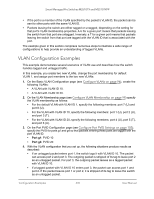
Smart Managed Pro Switches MS510TX and MS510TXPP 13. In the Size field, enter the size of the probe packets. The range is 64 to 1472. The default value is 64. 14. Click the Apply button. A traceroute request is sent to the specified IPv4 address or host name. The results are displayed below the configurable data in the Results field. If a reply to the traceroute is received, a message similar to the following one is displayed: 1 10.5.225.33 20 ms 10 ms 30 ms 2 10.5.225.225 10 ms 10 ms 10 ms 3 192.254.254.3 10 ms 30 ms 20 ms Hop Count = 3 Test attempt = 9 Test Success = 3 Send an IPv6 Traceroute Use this page to tell the switch to send a traceroute request to a specified IPv6 address or host name. You can use this to discover the paths that packets take to a remote destination. Once you click the Apply button, the switch sends a traceroute and the results are displayed below the configurable data. To send an IPv6 traceroute: 1. Connect your computer to the same network as the switch. You can use a WiFi or wired connection to connect your computer to the network, or connect directly to a switch that is off-network using an Ethernet cable. 2. Launch a web browser. 3. In the address field of your web browser, enter the IP address of the switch. If you do not know the IP address of the switch, see Access the Switch on page 14. The login window opens. 4. Enter the switch's password in the Password field. The default password is password. The System Information page displays. 5. Select Maintenance > Troubleshooting > Traceroute IPv6. The Traceroute IPv6 page displays. 6. In the IPv6 Address/Host Name field, enter the IPv6 address or host name of the device for which the path must be discovered. 7. In the Probes Per Hop field, enter the number of probes per hop. The range is 1 to 10. The default value is 3. 8. In the Max TTL field, enter the maximum time to live (TTL) for the destination. The range is 1 to 255. The default value is 30. Maintain the Switch and Perform 330 Troubleshooting User Manual
-
 1
1 -
2
-
3
-
4
-
5
-
6
-
7
-
8
-
9
-
10
-
11
-
12
-
13
-
14
-
15
-
16
-
17
-
18
-
19
-
20
-
21
-
22
-
23
-
24
-
25
-
26
-
27
-
28
-
29
-
30
-
31
-
32
-
33
-
34
-
35
-
36
-
37
-
38
-
39
-
40
-
41
-
42
-
43
-
44
-
45
-
46
-
47
-
48
-
49
-
50
-
51
-
52
-
53
-
54
-
55
-
56
-
57
-
58
-
59
-
60
-
61
-
62
-
63
-
64
-
65
-
66
-
67
-
68
-
69
-
70
-
71
-
72
-
73
-
74
-
75
-
76
-
77
-
78
-
79
-
80
-
81
-
82
-
83
-
84
-
85
-
86
-
87
-
88
-
89
-
90
-
91
-
92
-
93
-
94
-
95
-
96
-
97
-
98
-
99
-
100
-
101
-
102
-
103
-
104
-
105
-
106
-
107
-
108
-
109
-
110
-
111
-
112
-
113
-
114
-
115
-
116
-
117
-
118
-
119
-
120
-
121
-
122
-
123
-
124
-
125
-
126
-
127
-
128
-
129
-
130
-
131
-
132
-
133
-
134
-
135
-
136
-
137
-
138
-
139
-
140
-
141
-
142
-
143
-
144
-
145
-
146
-
147
-
148
-
149
-
150
-
151
-
152
-
153
-
154
-
155
-
156
-
157
-
158
-
159
-
160
-
161
-
162
-
163
-
164
-
165
-
166
-
167
-
168
-
169
-
170
-
171
-
172
-
173
-
174
-
175
-
176
-
177
-
178
-
179
-
180
-
181
-
182
-
183
-
184
-
185
-
186
-
187
-
188
-
189
-
190
-
191
-
192
-
193
-
194
-
195
-
196
-
197
-
198
-
199
-
200
-
201
-
202
-
203
-
204
-
205
-
206
-
207
-
208
-
209
-
210
-
211
-
212
-
213
-
214
-
215
-
216
-
217
-
218
-
219
-
220
-
221
-
222
-
223
-
224
-
225
-
226
-
227
-
228
-
229
-
230
-
231
-
232
-
233
-
234
-
235
-
236
-
237
-
238
-
239
-
240
-
241
-
242
-
243
-
244
-
245
-
246
-
247
-
248
-
249
-
250
-
251
-
252
-
253
-
254
-
255
-
256
-
257
-
258
-
259
-
260
-
261
-
262
-
263
-
264
-
265
-
266
-
267
-
268
-
269
-
270
-
271
-
272
-
273
-
274
-
275
-
276
-
277
-
278
-
279
-
280
-
281
-
282
-
283
-
284
-
285
-
286
-
287
-
288
-
289
-
290
-
291
-
292
-
293
-
294
-
295
-
296
-
297
-
298
-
299
-
300
-
301
-
302
-
303
-
304
-
305
-
306
-
307
-
308
-
309
-
310
-
311
-
312
-
313
-
314
-
315
-
316
-
317
-
318
-
319
-
320
-
321
-
322
-
323
-
324
-
 325
325 -
 326
326 -
 327
327 -
 328
328 -
 329
329 -
 330
330 -
 331
331 -
 332
332 -
 333
333 -
 334
334 -
 335
335 -
336
-
337
-
338
-
339
-
340
-
341
-
342
-
343
-
344
-
345
-
346
-
347
-
348
-
349
-
350
-
351
-
352
-
353
-
354
-
355
 |
 |
