LiftMaster JHDC Installation Manual - English French Spanish - Page 26
Cable Tension Monitors, Install the Cable Tension Monitor, OVERVIEW
 |
View all LiftMaster JHDC manuals
Add to My Manuals
Save this manual to your list of manuals |
Page 26 highlights
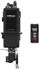
Cable Tension Monitors Install the Cable Tension Monitor(s) (Optional) TWO CABLE TENSION MONITORS MAY BE CONNECTED TO THIS OPERATOR. THE CABLE TENSION MONITORS DETECT ANY SLACK THAT MAY OCCUR IN THE CABLES AND WILL RESPOND ACCORDINGLY. NOTE: ONLY USE THE LIFTMASTER CABLE TENSION MONITORS, AS THEY HAVE BEEN TESTED AND APPROVED FOR THIS SYSTEM. See "Accessories" on page 63. Cable Drum 1. Make sure the door cable is approximately 1"-2" (25-50 mm) from the mounting surface. Door adjustments or shimming may be required to achieve proper depth for the door cable. The bracket must be flush with the mounting surface. Drum 2. Position the cable tension monitor as cloCsabeleto the drum as possible. The optimal distance of the cable from the wall surface is no more than 2.5" (6.35 cm), and be sure the roller extends 1/8"-1/4" past the cable. Make sure the cable tension monitor and roller is free from any obstructions in all positions of operation. Drum Cable tension monitor Drum Approx. 1-2" 25-60cm C(wahbelne dtoeonrsiisocnlosed) monitor NOTE: There must be no obstructions in the installation area that prevent the cable tension monitor from closing completely when slack is detected. NOTE: Cable tension monitors must either be anchored to concrete, or a wood stud with appropriate fasteners. If neither are available, toggle bolt style drywall anchors with at least a 50 lbs rating are acceptable. Cable Tension Monitor 1/4"-3/8" (6.4-95 mm) Cable Tension Monitor Roller Approx. 1-2" 25-60cm (when door is closed) 21 22 23 24 21 22 23 24 3. Run bell wire to the door operator junction box, and dowOnVtEoRVIEW the control box through conduit as shown on the right. SBC SBC 4. OnScBCe the controller is insSBtCalled, connect the bell wires parallel to the CTM and CMN terminals on the terminals on thCeMNcontroller (polarity is not importCMaAOnBNLtIET).OTSRENSeSeIO"NWall Controller Installation" on page 23 for installation information. Once inCsTtMalled, follow these steps to connect the wiring. CMN Cable TensioCnTM Monitor CMN CABLE TENSION MONITORS Cable Tension Monitors 5. CCoMnNnect the bell wires in parallel to the CTM and CMN terminals on the controller (polarity is not important). To simplify installation, the cable tension monitors can bCeeabwleirTeednstioongether in the operator junction box, with only one a pair of bell wires running down to the controller. Monitor Roller 6. Repeat steps 1-5 for the opposite sid1(e6/4.4o"--39f/5t8h"memd) oor. Both cable tension monitors must be installed for proper operation. NOTE: Cable must have tension through entire door travel. Make sure there is no slSaBcCk in cable on opposite side of door during normal operation. If slack occurs during cables daosorer qtruaCMivrAeOeBdNl,L.IaETdOTjREuNSsStION OVERVIEW Cab 1/4"-3/8 (6.4-95 OVE e Cable Tension Monitors e a 26
-
 1
1 -
2
-
3
-
4
-
5
-
6
-
7
-
8
-
9
-
10
-
11
-
12
-
13
-
14
-
15
-
16
-
17
-
18
-
19
-
20
-
 21
21 -
 22
22 -
 23
23 -
 24
24 -
 25
25 -
 26
26 -
 27
27 -
 28
28 -
 29
29 -
 30
30 -
 31
31 -
32
-
33
-
34
-
35
-
36
-
37
-
38
-
39
-
40
-
41
-
42
-
43
-
44
-
45
-
46
-
47
-
48
-
49
-
50
-
51
-
52
-
53
-
54
-
55
-
56
-
57
-
58
-
59
-
60
-
61
-
62
-
63
-
64
-
65
-
66
-
67
-
68
-
69
-
70
-
71
-
72
-
73
-
74
-
75
-
76
-
77
-
78
-
79
-
80
-
81
-
82
-
83
-
84
-
85
-
86
-
87
-
88
-
89
-
90
-
91
-
92
-
93
-
94
-
95
-
96
-
97
-
98
-
99
-
100
-
101
-
102
-
103
-
104
-
105
-
106
-
107
-
108
-
109
-
110
-
111
-
112
-
113
-
114
-
115
-
116
-
117
-
118
-
119
-
120
-
121
-
122
-
123
-
124
-
125
-
126
-
127
-
128
-
129
-
130
-
131
-
132
-
133
-
134
-
135
-
136
-
137
-
138
-
139
-
140
-
141
-
142
-
143
-
144
-
145
-
146
-
147
-
148
-
149
-
150
-
151
-
152
-
153
-
154
-
155
-
156
-
157
-
158
-
159
-
160
-
161
-
162
-
163
-
164
-
165
-
166
-
167
-
168
-
169
-
170
-
171
-
172
-
173
-
174
-
175
-
176
-
177
-
178
-
179
-
180
-
181
-
182
-
183
-
184
-
185
-
186
-
187
-
188
-
189
-
190
-
191
-
192
-
193
-
194
-
195
-
196
-
197
-
198
-
199
-
200
-
201
-
202
-
203
-
204
-
205
-
206
-
207
-
208
-
209
-
210
-
211
-
212
-
213
-
214
-
215
-
216
 |
 |
