LiftMaster HDSL24UL Installation Manual - English - Page 22
Step 9 Install the cover, Step 10 Install Warning Signs, The basic installation is complete.
 |
View all LiftMaster HDSL24UL manuals
Add to My Manuals
Save this manual to your list of manuals |
Page 22 highlights
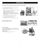
INSTALLATION Step 9 Install the cover Before installing the cover, follow the instructions in the Adjustment section to adjust the limits, speed, and force. 1. Slide the cover over the operator. 2. Align the holes in the cover with the threaded holes in the operator's chassis and secure the cover with the provided screws. Screw Screw Step 10 Install Warning Signs Installers MUST install the UL required warning signs. The signs MUST be installed in plain view on both sides of each gate installed. Use the fastening holes in each corner to permanently secure the sign. The basic installation is complete. Place warning signs on both sides of the gate in clear view 22
-
 1
1 -
2
-
3
-
4
-
5
-
6
-
7
-
8
-
9
-
10
-
11
-
12
-
13
-
14
-
15
-
16
-
 17
17 -
 18
18 -
 19
19 -
 20
20 -
 21
21 -
 22
22 -
 23
23 -
 24
24 -
 25
25 -
 26
26 -
 27
27 -
28
-
29
-
30
-
31
-
32
-
33
-
34
-
35
-
36
-
37
-
38
-
39
-
40
-
41
-
42
-
43
-
44
-
45
-
46
-
47
-
48
-
49
-
50
-
51
-
52
-
53
-
54
-
55
-
56
-
57
-
58
-
59
-
60
 |
 |

22
Step 9 Install the cover
Before installing the cover, follow the instructions in the Adjustment
section to adjust the limits, speed, and force.
1.
Slide the cover over the operator.
2.
Align the holes in the cover with the threaded holes in the operator's
chassis and secure the cover with the provided screws.
Screw
Screw
Step 10 Install Warning Signs
Installers MUST install the UL required warning signs. The signs MUST
be installed in plain view on
both sides
of each gate installed. Use the
fastening holes in each corner to permanently secure the sign.
Place warning signs
on
both sides
of the
gate in clear view
The basic installation is complete.
INSTALLATION