LiftMaster HDSL24UL Installation Manual - English - Page 21
Wired setup, Bipart delay/synchronized close, BIPART DELAY
 |
View all LiftMaster HDSL24UL manuals
Add to My Manuals
Save this manual to your list of manuals |
Page 21 highlights
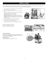
INSTALLATION Wired setup Use only the same operator models in a dual gate setup. Before digging, contact local underground utility locating companies. Use PVC conduit to prevent damage to cables. 1. Disconnect ALL power to the operator and turn OFF the battery and AC power switches. 2. Trench across driveway to bury the shielded twisted pair cable. 3. Connect the wires from the shielded twisted pair cable to the Com Link terminals on the primary gate operator control board. NOTE: We recommend that all accessories, except entrapment protection devices, and board configurations are set on the primary operator. 4. Route the shielded twisted pair cable to the secondary gate operator's control board. 5. Connect the wires from the shielded twisted pair cable to the Com Link terminals on the secondary control board (Com Link A to Com Link A and Com Link B to Com Link B). Ground the shield of the cable to the chassis ground of one operator. 6. Connect ALL power to the operator and turn ON the battery and AC power switches. DUAL GATE WIRE TYPE (SHIELDED TWISTED PAIR CABLE) 22AWG up to 200 feet (61 m) 18AWG - 200-1000 feet (61-305 m) Wire must be rated at 30 Volt minimum Com Link Data A Com Link Data B Com Link Data A Com Link Data B Bipart delay/synchronized close The BIPART DELAY switch is used only with dual gate applications and serves two functions: • BIPART DELAY Not applicable for slide gate applications. • SYNCHRONIZED CLOSE To synchronize the closing of the gates, set the BIPART DELAY switch to ON for both operators. 21
-
 1
1 -
2
-
3
-
4
-
5
-
6
-
7
-
8
-
9
-
10
-
11
-
12
-
13
-
14
-
15
-
 16
16 -
 17
17 -
 18
18 -
 19
19 -
 20
20 -
 21
21 -
 22
22 -
 23
23 -
 24
24 -
 25
25 -
 26
26 -
27
-
28
-
29
-
30
-
31
-
32
-
33
-
34
-
35
-
36
-
37
-
38
-
39
-
40
-
41
-
42
-
43
-
44
-
45
-
46
-
47
-
48
-
49
-
50
-
51
-
52
-
53
-
54
-
55
-
56
-
57
-
58
-
59
-
60
 |
 |
