LiftMaster HDSL24UL Installation Manual - English - Page 18
Plug In Transformer Power, AC Power Switch, Battery Switch
 |
View all LiftMaster HDSL24UL manuals
Add to My Manuals
Save this manual to your list of manuals |
Page 18 highlights
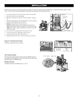
INSTALLATION All control wiring used to connect external devices to Class 2 circuits of the operator must be (QPTZ) Power-Limited Circuit Cables, Type CL2, CL2P, CL2R, or CL2X or other cable with equivalent or better electrical, mechanical, and flammability ratings. 1. Turn off the AC power from the main power source circuit breaker. 2. Run the AC power wires to the operator. 3. Make sure the operator AC switch is in the OFF position, see page 18. 4. Remove the junction box cover from the electrical box by loosening the screws and sliding the cover to the side. 5. 120 Vac: Factory default is 120 Vac. Skip to 5. 240 Vac: Unplug the power wiring connector from the 120 Vac socket (factory default location) and plug it into the 240 Vac socket. NOTE: The accessory outlets are disabled and cannot be used with the 240 Vac option. 6. Connect the incoming green wire to the earth ground nut. 7. Connect the white wire to NEUTRAL using a wire nut. 8. Connect the black wire to HOT using a wire nut. 9. Replace the junction box cover. Ensure the wires are not pinched. EMI Board Power Wiring Connector White Black Incoming Power Green ground wire Plug In Transformer Power Wire plug in transformer power as shown. Control Board AC Power Switch The AC switch on the operator turns the incoming 120/240 Vac power ON or OFF. The AC switch ONLY turns off AC power to the control board and DOES NOT turn off battery power. Battery Switch The battery switch turns the battery power on or off. Set switch to WALL XFMR Plug in transformer AC Power Switch Battery Switch 18
-
 1
1 -
2
-
3
-
4
-
5
-
6
-
7
-
8
-
9
-
10
-
11
-
12
-
 13
13 -
 14
14 -
 15
15 -
 16
16 -
 17
17 -
 18
18 -
 19
19 -
 20
20 -
 21
21 -
 22
22 -
 23
23 -
24
-
25
-
26
-
27
-
28
-
29
-
30
-
31
-
32
-
33
-
34
-
35
-
36
-
37
-
38
-
39
-
40
-
41
-
42
-
43
-
44
-
45
-
46
-
47
-
48
-
49
-
50
-
51
-
52
-
53
-
54
-
55
-
56
-
57
-
58
-
59
-
60
 |
 |
