LiftMaster HDSL24UL Installation Manual - English
LiftMaster HDSL24UL Manual
 |
View all LiftMaster HDSL24UL manuals
Add to My Manuals
Save this manual to your list of manuals |
LiftMaster HDSL24UL manual content summary:
- LiftMaster HDSL24UL | Installation Manual - English - Page 1
III, and IV vehicular slide gate applications. • Visit LiftMaster.com to locate a professional installing dealer in your area. • This gate operator is compatible with MyQ® and Security+ 2.0® accessories. Access installation and technical support guides or register this product 1. Take a photo of - LiftMaster HDSL24UL | Installation Manual - English - Page 2
Instructions 38 Maintenance Chart 39 Batteries 39 Drive Train 39 TROUBLESHOOTING 40 Diagnostic Codes 40 Control Board LEDs 41 Troubleshooting Chart 42 SOLAR PANELS 45 Step 6 Solar Panel(s 45 REPAIR PARTS manual and follow all safety instructions. • DO NOT attempt repair or service - LiftMaster HDSL24UL | Installation Manual - English - Page 3
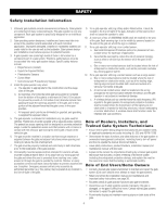
intended to service the general LiftMaster monitored external edge sensors, see page 50 for acceptable sensors. IMPORTANT SAFETY INSTRUCTIONS To reduce the risk of INJURY or DEATH: • READ AND FOLLOW ALL INSTRUCTIONS. • NEVER let children operate or play with gate controls. Keep the remote control - LiftMaster HDSL24UL | Installation Manual - English - Page 4
of the gate operator. • Leave safety instructions, product literature, installation manual and maintenance manual with end user. 8. Permanently mounted access controls intended for users to activate, must be located at least 6 feet (1.8 m) away from any moving part of the gate and where the user - LiftMaster HDSL24UL | Installation Manual - English - Page 5
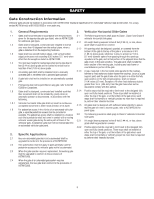
the vertical plane, when a gate is detached from the supporting hardware. 3.1.2 All openings shall be designed, guarded, or screened existing gate latch shall be disabled when a manually operated gate is retrofitted with a powered the gate will enter a receiver guide, refer to ASTM F2200 for panel - LiftMaster HDSL24UL | Installation Manual - English - Page 6
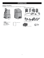
, Chain #40 - 30 feet with #40 master link, Eye Bolt Kit MONITORED ENTRAPMENT PROTECTION DEVICES Operator Warning Signs (2) Cover Installation Manual LiftMaster Monitored Retro-Reflective Photoelectric Sensor Model LMRRUL (1) 5 ft. Edge Sensor Kit Model S505AL (1) Battery 12 Vdc 7AH (2) Key - LiftMaster HDSL24UL | Installation Manual - English - Page 7
. Maximum Daily Cycle Rate Continuous for line voltage, not continuous for solar Maximum Duty Cycle Continuous Operating Temperature Without Heater: -20°C to 60 External Entrapment Protection Device Inputs (non-contact Main board - up to 2 close entrapment protection devices and 1 - LiftMaster HDSL24UL | Installation Manual - English - Page 8
not required but are recommended. Before installing your Access Control Device(s) be sure to complete a site survey and determine the best device for your site needs. Access Control Device Vehicle Loops Outside Property SAFETY CATCH ROLLERS Install catch rollers - LiftMaster HDSL24UL | Installation Manual - English - Page 9
INSTALLATION • To AVOID damaging gas, power or other underground utility lines, • ALWAYS wear protective gloves and eye protection when changing contact underground utility locating companies BEFORE digging more the battery or working around the battery compartment. than 18 inches (46 cm) deep. - LiftMaster HDSL24UL | Installation Manual - English - Page 10
INSTALLATION Step 1 Determine Location for Operator Check the national and local building codes before installation. Standard Installation 1. The gate operator should be installed near the front roller of the gate. Lay out the concrete pad. 2. Install the electrical conduit. 3. Pour a concrete pad ( - LiftMaster HDSL24UL | Installation Manual - English - Page 11
INSTALLATION Step 2 Install the Operator Attach the operator to the concrete pad with appropriate fasteners. The gate operator should be installed near the front roller of the gate or near the back of the gate (in the OPEN position). The space between the gate and the output sprocket must be a - LiftMaster HDSL24UL | Installation Manual - English - Page 12
Chain Standard Installation DO NOT run the operator until instructed. 1. Manually open the gate and line up the front bracket so the chain will be level with the idler pulley and parallel to the ground. Weld the front bracket in this position. 2. Manually close the gate and line up the rear bracket - LiftMaster HDSL24UL | Installation Manual - English - Page 13
DO NOT run the operator until instructed. NOTE: This installation will require two extra idler pulleys. Make sure all exposed pinch points are guarded. Refer to Gate Construction Information on page 5. 1. Move the back pulley to the bottom hole in the operator. 2. Manually close the gate and align - LiftMaster HDSL24UL | Installation Manual - English - Page 14
INSTALLATION To prevent SERIOUS INJURY or DEATH from a moving gate: • ALL gate operator systems REQUIRE two independent entrapment protection systems for each entrapment zone. • Entrapment protection devices MUST be installed to protect anyone who may come near a moving gate. • Entrapment - LiftMaster HDSL24UL | Installation Manual - English - Page 15
operator, refer to the manual provided with your entrapment protection device. Test the inherent entrapment protection by following the Obstruction Test instructions page 25. See Wire complete installation site for your records Illustrations provided by DASMA Gate Systems Safety Guide 15 - LiftMaster HDSL24UL | Installation Manual - English - Page 16
device and how the device will function. Refer to the manual included with your entrapment protection device for more information. These may be wired to the expansion board. NOTE: Board inputs for entrapment protection devices are yellow. Control Board CLOSES EYES/INTERRUPT (2 Terminals) - LiftMaster HDSL24UL | Installation Manual - English - Page 17
be cleared and secured, at that time the unit may be returned to service. • ALL power wiring should be on a dedicated circuit and well protected power supply and control wiring MUST be run in separate conduits. SOLAR APPLICATIONS: For solar applications see page 48 in the Solar Panels section. - LiftMaster HDSL24UL | Installation Manual - English - Page 18
AC switch on the operator turns the incoming 120/240 Vac power ON or OFF. The AC switch ONLY turns off AC power to the control board and DOES NOT turn off battery power. Battery Switch The battery switch turns the battery power on or off. Set switch to WALL XFMR Plug - LiftMaster HDSL24UL | Installation Manual - English - Page 19
INSTALLATION Step 7 Connect Batteries 7AH Batteries The batteries are charged in the circuit by the integrated transformer. 1. Turn the AC power switch to OFF. 2. Turn the battery switch OFF . 3. Connect a jumper between the positive(+) terminal of the battery to the negative terminal(-) of the - LiftMaster HDSL24UL | Installation Manual - English - Page 20
any wireless entrapment protection devices required for the second operator. NOTE: We recommend that all accessories, except entrapment protection devices, and board configurations are set on the primary operator. 2. Press and release the LEARN button on the primary operator. The green XMITTER LED - LiftMaster HDSL24UL | Installation Manual - English - Page 21
the primary operator. 4. Route the shielded twisted pair cable to the secondary gate operator's control board. 5. Connect the wires from the shielded twisted pair cable to the Com Link terminals on the secondary control board (Com Link A to Com Link A and Com Link B to Com Link B). Ground the shield - LiftMaster HDSL24UL | Installation Manual - English - Page 22
INSTALLATION Step 9 Install the cover Before installing the cover, follow the instructions in the Adjustment section to adjust the limits, speed, and force. 1. Slide the cover over the operator. 2. Align the holes in the cover with the - LiftMaster HDSL24UL | Installation Manual - English - Page 23
close the gate. The force is adjusted automatically when you program the limits but should be fine tuned using the REVERSAL FORCE dial on the control board (refer to Fine Tune the Force section) to compensate for environmental changes. The limit setup LEDs (located next to the SET OPEN and SET CLOSE - LiftMaster HDSL24UL | Installation Manual - English - Page 24
forces. 2. Perform the Obstruction Test, see page 25. Fine Tune the Force Once the initial limits have been set, the REVERSAL FORCE DIAL on the control board is used for fine tuning the force where wind or environmental changes may affect the gate travel. The REVERSAL FORCE DIAL is set to minimum - LiftMaster HDSL24UL | Installation Manual - English - Page 25
should stop and reverse upon contact with the object or hand. If the gate does not reverse, reduce the force setting by turning the force control slightly counterclockwise. The gate should have enough force to reach both the open and close limits, but MUST reverse after contact with an object or - LiftMaster HDSL24UL | Installation Manual - English - Page 26
button on the control station three times. NOTE: The operator will time out of programming mode after 30 seconds. NOTICE: This device complies with Part 15 of and, if not installed and used in accordance with the instructions, may cause harmful interference to radio communications. However, there - LiftMaster HDSL24UL | Installation Manual - English - Page 27
up an account and follow the app instructions to add your gate operator. 5. The LiftMaster Internet Gateway will pair to the operator if it is within range and the operator will beep if programming is successful. The gate operator can then be controlled through the myQ® App. 3. Press LEARN button - LiftMaster HDSL24UL | Installation Manual - English - Page 28
the KPW5/KPW250 manual for complete programming instructions). The Constant Pressure protection devices include LiftMaster monitored photoelectric sensors and LiftMaster monitored wired and release the button (approximately 6 seconds). All remote control codes are now erased. Erase Limits 1. To erase - LiftMaster HDSL24UL | Installation Manual - English - Page 29
or control). close (timer or control). close (timer or control). immediately manually tampered with by being pushed off of close limit. Cycle Quantity Feedback Use during servicing only to determine operator cycles. Use during servicing only to determine operator cycles. Use during servicing - LiftMaster HDSL24UL | Installation Manual - English - Page 30
to 180 seconds, 0 seconds is OFF. NOTE: Any radio command, single button control, or CLOSE command on the control board prior to the TTC expiring will close the gate. The TTC is reset by any signals from the open controls, loops, close edges, and close photoelectric sensors (IR's). 11 REVERSAL FORCE - LiftMaster HDSL24UL | Installation Manual - English - Page 31
to disable gate operation. Use this switch before servicing the gate or manually disconnecting the gate. The stop LED will be Manual Release Handle Relay Adapter Board and Terminal Block Access To access the relay adapter board and terminal block, loosen the two screws of the control board - LiftMaster HDSL24UL | Installation Manual - English - Page 32
and E reset the operator. After the operator is reset, normal functions will resume. Remote control There are 3 different options for programming the remote control depending on how you would like the remote control to function, see page 26. Single Button Open Only When gate is in the closed - LiftMaster HDSL24UL | Installation Manual - English - Page 33
gate to open. • Opens a closed or closing gate and holds open an open gate, if maintained, pauses Timer-to-Close at OPEN limit. Exit Com Control board SHADOW (2 Terminals) This input is used for external shadow loop detector when loop is positioned under the swing of the gate. • Holds open gate at - LiftMaster HDSL24UL | Installation Manual - English - Page 34
5 seconds after motion. • UNSWITCHED: 24 Vdc voltage out to power accessories, always ON. MAIN CONTROL BOARD Three Button Control Station Open Close Stop N.C. Com Fire Dept Com Fire Department MAIN CONTROL BOARD Accessory Power Switched Com (-) Acc power +24 Vdc Com (-) Acc power +24 Vdc Accessory - LiftMaster HDSL24UL | Installation Manual - English - Page 35
flash 5 times, then stop, then the LED 2 will flash once). 8. J6 and J7 inputs: Communication bus connects control board, expansion board, or relay adapter board. Also connects LiftMaster wireless edge receiver LMWEKITU. NOTE: ONLY one wireless edge receiver may be connected to an operator. Up to - LiftMaster HDSL24UL | Installation Manual - English - Page 36
Energizes when AC power or solar power is present. There is ON Energizes if gate is manually tampered with by being pushed below. ON ON ON stored on the control board). See below. * Cycle count First, 1,000 and 9,999,000 cycles. After servicing, set Aux Relay switches back to their appropriate - LiftMaster HDSL24UL | Installation Manual - English - Page 37
chart below and the corresponding image for a description of the expansion board inputs. 1 Wireless edge, control board, or Connection for wireless edge receiver, control board or relay adapter board. NOTE: ONLY one wireless relay adapter board edge receiver may be connected to an operator. Up to - LiftMaster HDSL24UL | Installation Manual - English - Page 38
let children operate or play with gate controls. Keep the remote control away from children. • ALWAYS keep PROPERLY MAINTAINED. Read this manual carefully. Have a qualified service person make repairs to gate use ONLY LiftMaster part 29-NP712 for replacement batteries. • SAVE THESE INSTRUCTIONS. • - LiftMaster HDSL24UL | Installation Manual - English - Page 39
solar, battery) to the operator before servicing. DESCRIPTION TASK CHECK AT LEAST ONCE EVERY Entrapment Protection Devices Warning Signs Manual diagnostic history for identification of intermittent problems Replace MONTH 6 MONTHS 3 YEARS years. Use only LiftMaster part 29-NP712 for replacement - LiftMaster HDSL24UL | Installation Manual - English - Page 40
TROUBLESHOOTING To protect against fire and electrocution: • DISCONNECT power (AC or solar and battery) BEFORE installing or servicing operator. For continued protection against fire: • Replace ONLY with fuse of same type and rating. Diagnostic Codes To View the Codes The codes will show - LiftMaster HDSL24UL | Installation Manual - English - Page 41
TROUBLESHOOTING Control Board LEDs INPUT OFF POWER ON STATUS LEDS OFF state AC charger or Solar power available BATT OFF CHARGING inactive ON Input active BLINK Input active on other operator or expansion board OFF Input inactive ON Input active BLINK Input active on other operator - LiftMaster HDSL24UL | Installation Manual - English - Page 42
TROUBLESHOOTING Troubleshooting Chart SYMPTOM Operator does not run and diagnostic display not on. Control board powers up, but motor does not run. Gate moves, but cannot set correct limits. POSSIBLE CAUSES a. No power to control board b. Open fuse c. If on battery power only, low or dead - LiftMaster HDSL24UL | Installation Manual - English - Page 43
TROUBLESHOOTING command. Alarm beeps when running. Expansion board function not controlling gate. POSSIBLE CAUSES a. Open control active b. Vehicle loop detector active c. must be 23 Vdc or higher. Charge batteries by AC or solar power or replace batteries. e. Check Fire Dept input f. Check Timer - LiftMaster HDSL24UL | Installation Manual - English - Page 44
batteries d. Solar panels are not getting enough sunlight a. Insufficient panel wattage b. Excessive accessory power draw c. Battery capacity too low SOLUTIONS a. Check that maglock is wired to N.C. and COM terminals. Check that maglock has power (do not power maglock from control board accessory - LiftMaster HDSL24UL | Installation Manual - English - Page 45
batteries in the given zones as shown on the map below. Local geography and weather conditions may require additional solar panels. Solar powered gate operator installations are not supported in northern climates due to cold weather and a reduced number of hours of sunlight during the winter months - LiftMaster HDSL24UL | Installation Manual - English - Page 46
guide All performance metrics are estimates and are subject to change at any time. Actual results will vary due to variables specific to the site. Typical System Standby Battery Current Consumption (mA) System voltage Main board with no radios programmed One or more LiftMaster® remote controls - LiftMaster HDSL24UL | Installation Manual - English - Page 47
panel(s) MUST be installed facing south. Use a compass to determine direction. Below are general instructions for installing the solar panel(s). Your installation may vary slightly depending on the solar panel purchased. 1. Position the mounting bracket on the mounting surface. Mark and drill holes - LiftMaster HDSL24UL | Installation Manual - English - Page 48
, HD Gates K41-0102-000 33AH Batteries Black wire from battery harness 33AH, HD Gates K41-0102-000 7AH Batteries Set Switch to SOLAR Battery Wiring Control Board 20W APPLICATION IN SERIES 40W APPLICATION IN SERIES 60W APPLICATION IN SERIES 10W 10W 10W 10W 20W 20W 10W 10W 20W 20W 10W - LiftMaster HDSL24UL | Installation Manual - English - Page 49
19-40240D K77-36764 K07-50637 K41-0093-000 K41-0097-000 K41-0102-000 40-39235 Wire Harness Kit, HD Gates Wire Harness - control board to expansion board Gear Box Vent Plug #40 Master Link #40 Chain - 10 feet Hardware Kit (chain bolt and chain bracket) Chain Bolt Reset Switch BLDC Motor - LiftMaster HDSL24UL | Installation Manual - English - Page 50
monitored wireless edge kit (transmitter and receiver) Model LMWEKITU LiftMaster monitored wireless edge transmitter Model LMWETXU Remote Controls LiftMaster offers a variety of LiftMaster remote controls to satisfy your application needs. Single-button to 4-button, visor or key chain. The - LiftMaster HDSL24UL | Installation Manual - English - Page 51
-mounting models CSL24UL, CSW24UL, control board. Not to be used as entrapment protection. Model LOOPDETLM Loop Detector Low power loop detectors mounted and wired separately inside control box. LiftMaster -Hour Battery, 12 Vdc. Ideal for solar applications and extended battery backup. Two required - LiftMaster HDSL24UL | Installation Manual - English - Page 52
Limited Warranty LiftMaster ("Seller") service center for warranty repair. You will be advised of shipping instructions when you call. Please include a brief description of the problem and returned pre-paid. Parts will be repaired or replaced with new or factory-rebuilt parts at Seller's sole option. - LiftMaster HDSL24UL | Installation Manual - English - Page 53
to desired OFF Close setting Bi-Part Delay Switch Synchronized Close: ON Synchronized Close: ON Speed Set the speed control dial on each operator to the desired setting, see page 24 for more details Expansion board ACCESSORY Remote Controls LiftMaster Internet Gateway Garage and Gate Monitor - LiftMaster HDSL24UL | Installation Manual - English - Page 54
the force. When limits are set properly the operator will automatically exit limit setting mode. Refer to the Adjustment section and follow the instructions for Speed Control, Fine Tune the Force, and Obstruction Test. Adjust the limits If the limits have already been set the operator will exit the - LiftMaster HDSL24UL | Installation Manual - English - Page 55
Wiring Diagram APPENDIX To protect against fire and electrocution: • DISCONNECT power (AC or solar and battery) BEFORE installing or servicing operator. CONTROL BOARD For continued protection against fire: • Replace ONLY with fuse of same type and rating. Jumper N.C. OPEN and COM: Hard Open ( - LiftMaster HDSL24UL | Installation Manual - English - Page 56
as it occurs, then disappear. LiftMaster System Installed System Informational External Entrapment Protection Inherent Entrapment Protection Code 31 34 35 36 37 38 40 41 42 43 44 45 46 47 48 50 53 54 60 61 62 63 64 65 66 Meaning Control board has experienced an internal failure. Absolute - LiftMaster HDSL24UL | Installation Manual - English - Page 57
obstruction did NOT occur, check alignment, inputs, and wiring on main control board IF an obstruction occurred, no action required. If an obstruction did NOT connections between the main board and the expansion board. Non-monitored contact closure devices are not supported. Make sure connected - LiftMaster HDSL24UL | Installation Manual - English - Page 58
beyond base of gate Pass / Fail All access controls at least 6 ft. from gate Pass / Fail from falling over if disconnected from supporting hardware Pass / Fail SWING / Fail Receiver guides recessed behind receiver post for receiver guides less than 8 2019 LiftMaster All Rights Reserved 300 Windsor - LiftMaster HDSL24UL | Installation Manual - English - Page 59
nearest the roadway (such as a gate support post) and the gate frame when the Any gap must be Interior posts, Guide posts protected. Install safety device to Photo eye (public side) Mount access control devices at least 6 ft (1.8 m) and operator manuals for complete instruction. Visit DAMSA - LiftMaster HDSL24UL | Installation Manual - English - Page 60
Contact Information LiftMaster.com LiftMaster Dealer Extranet: dealer.liftmaster.com/login LiftMaster Training Academy: liftmastertraining.com 800-528-2806 Mon-Fri 5:00 am to 6:00 pm MST 300 Windsor Drive Oak Brook, IL 60523 LiftMaster.com © 2019, The Chamberlain Group, Inc. - All Rights Reserved
-
 1
1 -
 2
2 -
 3
3 -
 4
4 -
 5
5 -
 6
6 -
 7
7 -
8
-
9
-
10
-
11
-
12
-
13
-
14
-
15
-
16
-
17
-
18
-
19
-
20
-
21
-
22
-
23
-
24
-
25
-
26
-
27
-
28
-
29
-
30
-
31
-
32
-
33
-
34
-
35
-
36
-
37
-
38
-
39
-
40
-
41
-
42
-
43
-
44
-
45
-
46
-
47
-
48
-
49
-
50
-
51
-
52
-
53
-
54
-
55
-
56
-
57
-
58
-
59
-
60
 |
 |

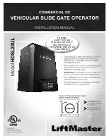
COMMERCIAL DC
VEHICULAR SLIDE GATE OPERATOR
INSTALLATION MANUAL
•
THIS PRODUCT MUST BE INSTALLED AND
SERVICED IN ACCORDANCE WITH THIS
MANUAL BY A TRAINED GATE SYSTEMS
TECHNICIAN ONLY.
•
This operator is for use on vehicular passage
gates ONLY and not intended for use on
pedestrian passage gates.
• HDSL24UL
is intended for use in Class I, II,
III, and IV vehicular slide gate applications.
•
Visit LiftMaster.com to locate a professional
installing dealer in your area.
•
This gate operator is compatible with MyQ
®
and Security+ 2.0
®
accessories.
LiftMaster
300 Windsor Drive
Oak Brook, IL 60523
Access installation and technical support
guides or register this product
Send it in
by texting
the photo to 71403.
Take a photo
of the
camera icon including
the points (
).
1.
2.
HDSL24ULTECH
Model
HDSL24UL