Invacare G5510 Owners Manual - Page 55
Inspecting the Bed, Electrical Connections
 |
View all Invacare G5510 manuals
Add to My Manuals
Save this manual to your list of manuals |
Page 55 highlights
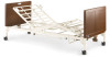
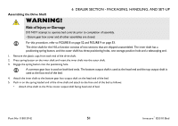
6 DEALER SECTION - PACKAGING, HANDLING, AND SET-UP Inspecting the Bed WARNING! Risk of Injury or Damage To avoid product damage, all electric cable connections MUST be aligned properly. Align locking levers with locking tabs for proper connection. All motors, power supply, connectors and wiring are located on the foot section. Connect power supply and pendant. Each connector is labeled with its specific function. 1. Inspect the power supply cord and motor cables for cuts or damage to the cord and/or plug. 2. Inspect the power supply for any damage to the connectors. 3. Ensure that all cable plugs are connected securely. 4. Make sure all cables are routed properly. 5. If damage is found, contact an Invacare Customer Service Representative to report the damaged items and request appropriate replacement parts or products. 6. Make all the electrical connections. Refer to Electrical Connections on page 54. 6.5 Electrical Connections When installing/removing pendant cable, port cover, or power supply to bus cable, ensure that flat edge of each connector is aligned with the flat edge of the corresponding connector. Invacare® G5510 Bed 54 Part No 1180159-E
-
 1
1 -
2
-
3
-
4
-
5
-
6
-
7
-
8
-
9
-
10
-
11
-
12
-
13
-
14
-
15
-
16
-
17
-
18
-
19
-
20
-
21
-
22
-
23
-
24
-
25
-
26
-
27
-
28
-
29
-
30
-
31
-
32
-
33
-
34
-
35
-
36
-
37
-
38
-
39
-
40
-
41
-
42
-
43
-
44
-
45
-
46
-
47
-
48
-
49
-
 50
50 -
 51
51 -
 52
52 -
 53
53 -
 54
54 -
 55
55 -
 56
56 -
 57
57 -
 58
58 -
 59
59 -
 60
60 -
61
-
62
-
63
-
64
-
65
-
66
-
67
-
68
-
69
 |
 |
