Invacare G5510 Owners Manual - Page 52
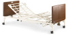
Assembling the Drive Shaft
 |
View all Invacare G5510 manuals
Add to My Manuals
Save this manual to your list of manuals |
Page 52 highlights
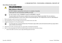
Assembling the Drive Shaft WARNING! 6 DEALER SECTION - PACKAGING, HANDLING, AND SET-UP Risk of Injury or Damage DO NOT attempt to operate bed controls prior to completion of assembly. - Ensure gear box cover and all other assemblies are closed. For this procedure, refer to FIGURE 8 on page 52 and FIGURE 9 on page 53. The drive shaft for the Hi/Lo function consists of two sections that are shipped unassembled. The inner shaft has a positioning spring button, and the outer shaft has three positioning holes, one storage position hole and a telescoping end. 1. Remove the plastic caps from each end of the drive shaft. 2. Press spring button on the inner shaft and insert the inner shaft into the outer shaft. 3. Engage the spring button into the positioning hole. A common gear box is used on both bed ends. The bottom output shaft is used at the head end and the top output shaft is used at the foot end of the bed. 4. Attach the inner shaft to the bottom gear box output shaft on the head end of the bed. 5. Push in on the spring loaded end of the drive shaft and attach to the foot end of the bed as follows: • Attach drive shaft to the Hi/Lo motor output shaft facing head end of bed. Part No 1180159-E 51 Invacare® G5510 Bed
-
 1
1 -
2
-
3
-
4
-
5
-
6
-
7
-
8
-
9
-
10
-
11
-
12
-
13
-
14
-
15
-
16
-
17
-
18
-
19
-
20
-
21
-
22
-
23
-
24
-
25
-
26
-
27
-
28
-
29
-
30
-
31
-
32
-
33
-
34
-
35
-
36
-
37
-
38
-
39
-
40
-
41
-
42
-
43
-
44
-
45
-
46
-
 47
47 -
 48
48 -
 49
49 -
 50
50 -
 51
51 -
 52
52 -
 53
53 -
 54
54 -
 55
55 -
 56
56 -
 57
57 -
58
-
59
-
60
-
61
-
62
-
63
-
64
-
65
-
66
-
67
-
68
-
69
 |
 |
