Invacare G5510 Owners Manual - Page 53
If necessary, shift bed end to right or left to align the Hi/Lo motor output shaft spring-loaded
 |
View all Invacare G5510 manuals
Add to My Manuals
Save this manual to your list of manuals |
Page 53 highlights
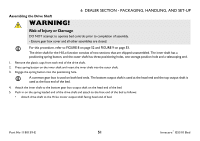
6 DEALER SECTION - PACKAGING, HANDLING, AND SET-UP Head End Head End Gear Box Inner Shaft Plastic Cap Foot End Drive Shaft Positioning Hole Storage Hole Foot End Gear Box Spring loaded End Spring Button Plastic Cap FIGURE 8 Assembling the Drive Shaft • Attach the Hi/Lo Motor to the foot end gear box as follows: i. Locate the Hi/Lo motor output shaft spring-loaded coupler. If necessary, shift bed end to right or left to align the Hi/Lo motor output shaft spring-loaded coupler with the foot end gear box. ii. Ensure the Hi/Lo motor output shaft spring-loaded coupler is properly aligned with the foot end gear box as shown in Detail "A" of FIGURE 9 on page 53. iii. Release the Hi/Lo motor output shaft spring-loaded coupler by pushing in against the Hi/Lo motor output shaft spring-loaded coupler and turning clockwise. iv. The coupling will release and engage the foot end top gear box output shaft cross pins. v. Ensure that all components are securely installed. Invacare® G5510 Bed 52 Part No 1180159-E
-
 1
1 -
2
-
3
-
4
-
5
-
6
-
7
-
8
-
9
-
10
-
11
-
12
-
13
-
14
-
15
-
16
-
17
-
18
-
19
-
20
-
21
-
22
-
23
-
24
-
25
-
26
-
27
-
28
-
29
-
30
-
31
-
32
-
33
-
34
-
35
-
36
-
37
-
38
-
39
-
40
-
41
-
42
-
43
-
44
-
45
-
46
-
47
-
 48
48 -
 49
49 -
 50
50 -
 51
51 -
 52
52 -
 53
53 -
 54
54 -
 55
55 -
 56
56 -
 57
57 -
 58
58 -
59
-
60
-
61
-
62
-
63
-
64
-
65
-
66
-
67
-
68
-
69
 |
 |
