Invacare G5510 Owners Manual - Page 47
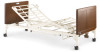
Foot Head Pull Tube, Head Center Mounting Latch, Center, Mounting
 |
View all Invacare G5510 manuals
Add to My Manuals
Save this manual to your list of manuals |
Page 47 highlights
6 DEALER SECTION - PACKAGING, HANDLING, AND SET-UP 1. Remove the head section (G50) and foot section (G54) of the bed from their packing cartons. 2. Place the head section on its side to your left so the center mounting latches are on the right. 3. Open the head section to a 45° to 90° angle for support. 4. Place foot section on its side to your right with the head section pull tube at the top of the assembly. The center mounting rivets should be on the left. Head Section Head Section Pull Tube Foot Section 45°-90° Center Mounting Latch Center Mounting Rivet FIGURE 3 Assembling the Head and Foot Sections For set-up purposes, the motors on the foot section as well as the crank handles should be on your right. 5. Place the head and foot sections approximately 90° from each other. 6. Hook the bottom head section center mounting latch to the bottom foot section center mounting rivet (FIGURE 4). 7. Hook the top head section center mounting latch to the top foot section center mounting rivet (FIGURE 4). Invacare® G5510 Bed 46 Part No 1180159-E
-
 1
1 -
2
-
3
-
4
-
5
-
6
-
7
-
8
-
9
-
10
-
11
-
12
-
13
-
14
-
15
-
16
-
17
-
18
-
19
-
20
-
21
-
22
-
23
-
24
-
25
-
26
-
27
-
28
-
29
-
30
-
31
-
32
-
33
-
34
-
35
-
36
-
37
-
38
-
39
-
40
-
41
-
 42
42 -
 43
43 -
 44
44 -
 45
45 -
 46
46 -
 47
47 -
 48
48 -
 49
49 -
 50
50 -
 51
51 -
 52
52 -
53
-
54
-
55
-
56
-
57
-
58
-
59
-
60
-
61
-
62
-
63
-
64
-
65
-
66
-
67
-
68
-
69
 |
 |
