Invacare G5510 Owners Manual - Page 48
Adjusting and Reconnecting the Head Pull Tube
 |
View all Invacare G5510 manuals
Add to My Manuals
Save this manual to your list of manuals |
Page 48 highlights
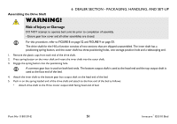
6 DEALER SECTION - PACKAGING, HANDLING, AND SET-UP It may be necessary to lift the head section or foot section slightly to secure the mounting latches and rivets. Center Mounting Latch Center Mounting Latch Center Mounting Rivet Center Mounting Rivet FIGURE 4 Inspecting - Assembling the Head and Foot Sections 8. After head and foot sections are connected, push the sections into a horizontal (straight) position while keeping the sections on their sides. Adjusting and Reconnecting the Head Section Pull Tube For this procedure, refer to FIGURE 5 on page 48. 1. To disconnect the head pull tube assembly from the side frame of the foot sections, remove the hitch pin, grommet/washer from the clevis pin (Detail "A"). 2. Extend the inner pull tube shaft manually until the sections button "clicks" into the adjustment hole of the outer pull tube. 3. Connect the pull tube end assembly to the lift arm of the head section as follows (Detail "B"): A. Insert the clevis pin into the lift arm slot. B. Replace the grommet/washer. C. Secure with hitch pin. Part No 1180159-E 47 Invacare® G5510 Bed
-
 1
1 -
2
-
3
-
4
-
5
-
6
-
7
-
8
-
9
-
10
-
11
-
12
-
13
-
14
-
15
-
16
-
17
-
18
-
19
-
20
-
21
-
22
-
23
-
24
-
25
-
26
-
27
-
28
-
29
-
30
-
31
-
32
-
33
-
34
-
35
-
36
-
37
-
38
-
39
-
40
-
41
-
42
-
 43
43 -
 44
44 -
 45
45 -
 46
46 -
 47
47 -
 48
48 -
 49
49 -
 50
50 -
 51
51 -
 52
52 -
 53
53 -
54
-
55
-
56
-
57
-
58
-
59
-
60
-
61
-
62
-
63
-
64
-
65
-
66
-
67
-
68
-
69
 |
 |
