Invacare G5510 Owners Manual
Invacare G5510 Manual
 |
View all Invacare G5510 manuals
Add to My Manuals
Save this manual to your list of manuals |
Invacare G5510 manual content summary:
- Invacare G5510 | Owners Manual - Page 1
Instructions: DO NOT PRINT THIS DRAWING This drawing is for informational purposes only. Document artwork controlled by Invacare DP .XX = .13mm MANUAL, USER .XXX = N/A N/A G5510 BED 1180159 .5 PART NO. DATE: 3/2/2018 REVISION E THIS IS THE PROPERTY OF INVACARE CORP. IT MUST NOT BE - Invacare G5510 | Owners Manual - Page 2
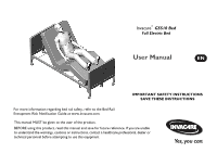
Invacare® G5510 Bed Full Electric Bed User Manual EN IMPORTANT SAFETY INSTRUCTIONS SAVE THESE INSTRUCTIONS For more information regarding bed rail safety, refer to the Bed Rail Entrapment Risk Notification Guide at www.invacare.com. This manual MUST be given to the user of the product. BEFORE - Invacare G5510 | Owners Manual - Page 3
trademarks are owned by or licensed to Invacare Corporation or its subsidiaries unless otherwise noted. Making Life's Experiences Possible is a registered trademark in the U.S.A. Sherwin-Williams is a registered trademark of The Sherwin-Williams Company. Invacare® G5510 Bed 2 Part No 1180159-E - Invacare G5510 | Owners Manual - Page 4
the Locking Function on the Locking Caster ...38 Electrical Connections ...38 Installing/Removing Pendant and/or Port Cover ...39 Using the Emergency Crank...41 Optional Bed Rails ...42 6 DEALER SECTION - PACKAGING, HANDLING, AND SET-UP 43 Part No 1180159-E 3 Invacare® G5510 Bed - Invacare G5510 | Owners Manual - Page 5
...56 Connect Power Supply ...58 Storing the Bed...58 7 TROUBLESHOOTING/MAINTENANCE - USER/DEALER 60 Troubleshooting Electrical...60 Troubleshooting Mechanical ...62 8 MAINTENANCE AND CLEANING 64 Maintenance Checklist ...64 Cleaning the Beds ...65 Invacare® G5510 Bed 4 Part No 1180159-E - Invacare G5510 | Owners Manual - Page 6
General 1 GENERAL 1.1 Symbols Warnings Signal words are used in this manual and apply to hazards or unsafe practices which could result in personal it is not avoided. Gives useful tips, recommendations and information for efficient, trouble-free use. Part No 1180159-E 5 Invacare® G5510 Bed - Invacare G5510 | Owners Manual - Page 7
requirements of prescribed product safety standards. Invacare® G5510 Bed Flammable Material Symbol (ISO 7010 W021) READ and Understand the User Manual before using the bed. (ISO 7010 - M002) General Current Protective Conductor Terminal IEC 60417 - 5957 For Indoor Use Only Part No 1180159-E - Invacare G5510 | Owners Manual - Page 8
made raising the entire mattress support platform MAX ISO 7000 - 0623 TOP ISO 7000 - 0621 FRAGILE ISO 7000 - 0626 KEEP DRY ISO 7000 - 2403 DO NOT STACK OVER 2 HIGH ISO 7000 - 0632 PERMITTED TEMPERATURE RANGE 0% ISO 7000 - 2620 PERMITTED HUMIDITY AREA Part No 1180159-E 7 Invacare® G5510 Bed - Invacare G5510 | Owners Manual - Page 9
For warranty service, please contact the dealer from whom you purchased your Invacare product. In the event you do not receive satisfactory warranty service, please write directly to Invacare at the TO COMPLY WITH STATE/PROVINCIAL LAWS AND REQUIREMENTS. Invacare® G5510 Bed 8 Part No 1180159-E - Invacare G5510 | Owners Manual - Page 10
2.1 Label Locations p/n 1171783 Rev E C p/n 1180180 Rev C p/n 1180192 Rev B Part No 1180159-E Not Shown: p/n 1193317 Rev A Serial Label with UDI p/n 1180206 Rev B p/n 1180206 Rev B 9 2 OVERVIEW p/n 1180195 Rev D (Located on both bed ends) p/n 1180201 Rev C p/n 1180137 Rev D Invacare® G5510 Bed - Invacare G5510 | Owners Manual - Page 11
also located on the emergency crank. p/n 1180199 Rev A p/n 1180193 Rev B p/n 1171789 Rev D *Labels shown for location and notice. Labels may change without notice. Contact your service provider or Invacare if label is missing or unreadable. Invacare® G5510 Bed 10 Part No 1180159-E - Invacare G5510 | Owners Manual - Page 12
71.6 kg) Head Section Weight 47 lbs (21.3 kg) Foot Section Weight 57 lbs (25.8 kg) Bed End Weight 54 lbs (24.5 kg) Safe Working Load 450 lbs (204 kg) Maximum Patient Weight 350 lbs , non condensing) Recommended Atmospheric Pressure 700 hpa to 1060 hpa Part No 1180159-E 11 Invacare® G5510 Bed - Invacare G5510 | Owners Manual - Page 13
through the use of electronic actuators. The G5510 bed is for assisting in diagnosis, monitoring, prevention, treatment, alleviation of disease, or compensation for an injury or disability in an indoor environment. Interaction of Patient with Bed Invacare® G5510 Bed 12 Part No 1180159-E - Invacare G5510 | Owners Manual - Page 14
material such as user manuals, service manuals or instruction sheets supplied with this product or optional equipment. The accessories in this table have been tested with the bed to meet the international bed standard IEC 60601-2-52: DESCRIPTION BED RAIL, FULL LENGTH BED RAIL, HALF LENGTH MODEL - Invacare G5510 | Owners Manual - Page 15
60601-2-52. They have been tested to comply with FDA Entrapment Guidelines when used with the G5510 bed and rails. DESCRIPTION MODEL NUMBER WEIGHT MATTRESS 5180 13.6 lbs (6.2 kg) 5185 26.6 at Sherwin Williams Automotive paint branches only. Invacare® G5510 Bed 14 Part No 1180159-E - Invacare G5510 | Owners Manual - Page 16
or instruction sheets supplied with this product or optional equipment. To avoid injury or product damage: Set-up and Assembly instructions MUST be performed by a qualified technician only. "Qualified Technician Only" sections are marked accordingly. Part No 1180159-E 15 Invacare® G5510 Bed - Invacare G5510 | Owners Manual - Page 17
qualified technician or Invacare for repair. Conditions such as restlessness, mental deterioration and dementia or seizure disorders (uncontrolled body movement), sleeping problems, and incontinence product. -Do not allow others to smoke near this product. Invacare® G5510 Bed 16 Part No 1180159-E - Invacare G5510 | Owners Manual - Page 18
regarding disposal of the device or components normally used in operation. The device does not generate waste or residue in operation. Any accessories not part of the device MUST be handled in accordance with the individual product marking for disposal. Part No 1180159-E 17 Invacare® G5510 Bed - Invacare G5510 | Owners Manual - Page 19
service personnel. Replacement parts for a double-insulated product must be identical to the parts they replace. A double-insulated product is marked with the words "DOUBLE INSULATION" or "DOUBLE INSULATED". The symbol ( ) is also able to be marked on the product. Invacare® G5510 Bed 18 Part - Invacare G5510 | Owners Manual - Page 20
such as the motors, pendant, junction boxes or gear boxes. No user serviceable parts are inside. Contact dealer or Invacare for repair/replacement. -Ensure gear box cover and all other assemblies are closed the power supply. Damage to cord will result. Part No 1180159-E 19 Invacare® G5510 Bed - Invacare G5510 | Owners Manual - Page 21
this bed's safety guide. Operating Information DANGER! Risk of Death, Injury, or Damage To avoid electrical damage, product damage, shock and/or personal injury: - Keep all product components and accessories a minimum of 12 inches away from hot or heated surfaces. Invacare® G5510 Bed 20 Part No - Invacare G5510 | Owners Manual - Page 22
underneath the bed or in between the raised bed frame components at any time. To avoid risk of death or injury from choking or ingestion of small parts or materials: - Closely supervise children, pets, or individuals with physical/mental disabilities. Part No 1180159-E 21 Invacare® G5510 Bed - Invacare G5510 | Owners Manual - Page 23
: - The product is not designed to be used as a patient transport. When transporting a patient, use an approved patient transport. Otherwise, injury or damage may result. Invacare® G5510 Bed 22 Part No 1180159-E - Invacare G5510 | Owners Manual - Page 24
product with locking casters in LOCKED position. The emergency crank will turn when motor is on and could cause personal injury or damage to the bed. - ALWAYS remove emergency crank(s) before performing electronic functions. Part No 1180159-E 23 Invacare® G5510 Bed - Invacare G5510 | Owners Manual - Page 25
of the bed are properly and securely in place. If any problems arise during the test, recheck all electrical connections and mechanical hook ups and then retest. If the product is not working properly, contact a qualified technician or Invacare for repair. Invacare® G5510 Bed 24 Part No 1180159 - Invacare G5510 | Owners Manual - Page 26
the bed to sit for several minutes. This will allow the protection function time to reset and restore bed function. Depending on the severity of the initial overheating, this could take up to 30 minutes. Pendant is constructed of latex-free materials. Part No 1180159-E 25 Invacare® G5510 Bed - Invacare G5510 | Owners Manual - Page 27
motors, pendant, power supply or gear boxes. No user serviceable parts are inside. Contact dealer or Invacare for repair/replacement. - To avoid product damage, all operation of the bed. - DO NOT use product with flammable gases. Explosion may occur. Invacare® G5510 Bed 26 Part No 1180159-E - Invacare G5510 | Owners Manual - Page 28
be centered on the bed frame. Otherwise, individuals may become trapped between the bed rail and the bed frame. -ALWAYS test to make sure that the side rails are properly and securely in place before using the bed. Otherwise, injury or damage may occur. Part No 1180159-E 27 Invacare® G5510 Bed - Invacare G5510 | Owners Manual - Page 29
in repositioning or transferring into or out of the bed. - NEVER allow patients to use trapeze or traction units as a total individual weight support. Trapeze units MUST be positioned on a bed end as near as possible to the center point of the bed end. Invacare® G5510 Bed 28 Part No 1180159-E - Invacare G5510 | Owners Manual - Page 30
should be evenly distributed over the surface of the bed. DO NOT lay, sit or lean in such a way that your entire body weight is placed only on raised head or foot sections of the bed. This includes when repositioning or transferring in or out of bed. Part No 1180159-E 29 Invacare® G5510 Bed - Invacare G5510 | Owners Manual - Page 31
or damage from crush hazard: - Caregivers MUST be aware of the bed-floor clearance when using lifts or any other device that assists the bed user that enters between the lowest component of the bed and the floor. Invacare® G5510 Bed Floor Bottom of Motor Guard 6.0 inches 30 Part No 1180159-E - Invacare G5510 | Owners Manual - Page 32
of this bed. - This bed should not be used adjacent to or stacked with other equipment. If adjacent or stacked use with other equipment is necessary, this bed should be observed to verify normal operation in the configuration in which it will be used. Part No 1180159-E 31 Invacare® G5510 Bed - Invacare G5510 | Owners Manual - Page 33
RF disturbances are controlled. The customer or the user of the G 5510 Bed can help prevent electromagnetic interference by maintaining a minimum distance between portable and mobile affected by absorption and reflection from structures, objects and people. Invacare® G5510 Bed 32 Part No 1180159-E - Invacare G5510 | Owners Manual - Page 34
5 Operation Bed End Locking Caster 5 OPERATION Bed Operation and Component Overview Head Section Slat Bed End Bed Frame Foot Section Part No 1180159-E Refer to Using the Emergency Crank on page 41 33 Refer to Operating the Bed on page 36 Invacare® G5510 Bed - Invacare G5510 | Owners Manual - Page 35
! Risk of Death, Injury or Damage To avoid pinching, crush and collapse hazards from bed deck contact with objects under the bed: - DO NOT place any objects or let any individual underneath the bed or in between the raised bed frame components at anytime. Invacare® G5510 Bed 34 Part No 1180159-E - Invacare G5510 | Owners Manual - Page 36
and mechanical hook ups. This bed uses a six function pendant for all bed operations. This bed is equipped with an emergency crank to allow operation in the event of a power outage. Keep power supply as close to the electrical outlet as possible. Part No 1180159-E 35 Invacare® G5510 Bed - Invacare G5510 | Owners Manual - Page 37
Foot Sections • To raise the head of the bed, press the "Head Up" button; To lower the head of the bed, press the "Head Down" button. • To raise the foot of the bed, press the "Foot Up" button; To lower the foot of the bed, press the "Foot Down" button. Invacare® G5510 Bed 36 Part No 1180159-E - Invacare G5510 | Owners Manual - Page 38
Head Section Foot Section Head Up Button Head Down Button Bed Up Button FIGURE 1 Operating the Bed 5 OPERATION Foot Up Button Foot Down Button Bed Down Button Part No 1180159-E 37 Invacare® G5510 Bed - Invacare G5510 | Owners Manual - Page 39
Function on the Locking Caster Locking the casters may not prevent the bed from moving on slick or slippery surfaces. • LOCK - Push down on connector. Pendant Connector Pendant/Port Cover Connection Flat Edge Invacare® G5510 Bed Port Cover Flat Edge of Port Cover FIGURE 3 Electrical - Invacare G5510 | Owners Manual - Page 40
to lock the connection in place (Detail "C"). Removing Pendant To disable the operation of electric beds, these models have pendants that can be removed and stored in a secure place. 1. To (Detail "E) and remove the port cover from the bus cable port. Part No 1180159-E 39 Invacare® G5510 Bed - Invacare G5510 | Owners Manual - Page 41
Cap Port Cover Detail "B" Connector Cap Detail "C" Pendant Cable Cap Detail "E" Connector Cap Detail "F" Connector Cap Connection MUST be tight Invacare® G5510 Bed Pendant Cable Bus Cable Port Connection MUST be tight FIGURE 4 Installing/Removing Pendant and/or Port Cover 40 Bus Cable Port - Invacare G5510 | Owners Manual - Page 42
Using the Emergency Crank 5 OPERATION If the bed needs to be adjusted manually due to a power outage or an electronic malfunction the Head Section To Raise/Lower the Entire Bed FIGURE 5 Using the Emergency Crank To Raise/Lower the Foot Section Part No 1180159-E 41 Invacare® G5510 Bed - Invacare G5510 | Owners Manual - Page 43
- Visit the FDA website at http://www.fda.gov to learn about the risks of entrapment. Review "A Guide to Bed Safety", published by the Hospital Bed Safety Workgroup. Use the link located under each bed rail product entry to access this bed's safety guide. Invacare® G5510 Bed 42 Part No 1180159-E - Invacare G5510 | Owners Manual - Page 44
Bed Ends 1. Remove any loose packing from the carton. 2. Bed End carton includes: • Two Bed Ends - Any surface of the bed ends may be gripped for handling except the gear box. Part No 1180159-E 43 Casters Packaging Carton Drive Shaft Bed Ends FIGURE 1 Unpacking the Bed Ends Invacare® G5510 Bed - Invacare G5510 | Owners Manual - Page 45
for handling. 3. Head Section carton includes: One Head End Section. Any part of the head section may be gripped for handling. Head End Section Shipping Carton Insert Foot End Section Insert Invacare® G5510 Bed Insert Power Supply FIGURE 2 Unpacking Foot and Head Sections 44 Shipping Carton - Invacare G5510 | Owners Manual - Page 46
Damage To avoid injury or damage: - DO NOT attempt to operate bed controls prior to completion of assembly. CAUTION! DO NOT use the slats as a hand hold to assemble/disassemble or move the bed, otherwise the slats may bend resulting in permanent damage. Part No 1180159-E 45 Invacare® G5510 Bed - Invacare G5510 | Owners Manual - Page 47
latches are on the right. 3. Open the head section to a 45° to 90° angle for support. 4. Place foot section on its side to your right with the head section pull tube at the top mounting latch to the top foot section center mounting rivet (FIGURE 4). Invacare® G5510 Bed 46 Part No 1180159-E - Invacare G5510 | Owners Manual - Page 48
pin, grommet/washer from the clevis pin (Detail "A"). 2. Extend the inner pull tube shaft manually until the sections button "clicks" into the adjustment hole of the outer pull tube. 3. Connect B. Replace the grommet/washer. C. Secure with hitch pin. Part No 1180159-E 47 Invacare® G5510 Bed - Invacare G5510 | Owners Manual - Page 49
Clevis Pin Head Section Pull Tube Outer Pull Tube Adjusting Hole Inner Pull Tube Nylon Washer FIGURE 5 Adjusting and Reconnecting the Head Section Pull Tube Invacare® G5510 Bed 48 Part No 1180159-E - Invacare G5510 | Owners Manual - Page 50
Stand one bed end as close to the head section as possible (Detail "A"). 2. Grasp the head section, by the side, and raise it until the rivets on the corner plates of the section are high enough to place into the corner locks on the bed end (Detail "A"). Part No 1180159-E 49 Invacare® G5510 Bed - Invacare G5510 | Owners Manual - Page 51
head of the bed, lift up on the head section and disengage the rivets out of the corner locks (Detail "A"). Bed End DETAIL "A" Head Section DETAIL "B" Foot Section Bed End Rivets Corner Locks Invacare® G5510 Bed FIGURE 7 Installing/Removing the Bed Ends 50 Rivets Corner Locks Part No 1180159 - Invacare G5510 | Owners Manual - Page 52
gear box is used on both bed ends. The bottom output shaft is used bed. 5. Push in on the spring loaded end of the drive shaft and attach to the foot end of the bed as follows: • Attach drive shaft to the Hi/Lo motor output shaft facing head end of bed. Part No 1180159-E 51 Invacare® G5510 Bed - Invacare G5510 | Owners Manual - Page 53
as follows: i. Locate the Hi/Lo motor output shaft spring-loaded coupler. If necessary, shift bed end to right or left to align the Hi/Lo motor output shaft spring-loaded coupler with the pins. v. Ensure that all components are securely installed. Invacare® G5510 Bed 52 Part No 1180159-E - Invacare G5510 | Owners Manual - Page 54
DETAIL "A" Bed End 6 DEALER SECTION - PACKAGING, HANDLING, AND SET-UP Hi/Lo Motor Output Shaft Spring-Loaded Coupler FOOT HEAD END END INPUT SIDE Drive Shaft Cover Gear Box Gear Box Input Drive Shaft (Covered) Part No 1180159-E FIGURE 9 Assembling the Drive Shaft 53 Invacare® G5510 Bed - Invacare G5510 | Owners Manual - Page 55
5. If damage is found, contact an Invacare Customer Service Representative to report the damaged items and request appropriate replacement parts or products. 6. Make all the electrical connections aligned with the flat edge of the corresponding connector. Invacare® G5510 Bed 54 Part No 1180159-E - Invacare G5510 | Owners Manual - Page 56
Recommended location for mattress keepers is on the end slat on either side of the bed. Pendant Connector Installing 1. Position mattress keeper over end slat as shown in Detail rail (Detail "B"). 2. Slide mattress keeper off of end slat (Detail "B"). Part No 1180159-E 55 Invacare® G5510 Bed - Invacare G5510 | Owners Manual - Page 57
stop in the DOWN position. • Position the mattress in-between the headboard of the head section and the footboard of the foot section. End Slat Invacare® G5510 Bed 56 Part No 1180159-E - Invacare G5510 | Owners Manual - Page 58
UP Position Detail "B" - Mattress Stop in DOWN Position Mattress Stop UP Mattress Stop DOWN FIGURE 12 Positioning Mattress Stop for SPS1080 Mattress and SPS1084 Mattress Part No 1180159-E 57 Invacare® G5510 Bed - Invacare G5510 | Owners Manual - Page 59
Store the bed in a dry area. WARNING! Risk of Injury or Damage To avoid product damage and personal injury: - DO NOT place other objects on top of the cartons. - Disconnect the pendant and/or power supply when not in use and store out of reach of children. CAUTION! Invacare® G5510 Bed 58 Part No - Invacare G5510 | Owners Manual - Page 60
of the slat located above the support brace bed. Power Supply Cable DETAIL "A" Power Supply DETAIL "B" Preferable location to secure power supply is this slat above the support brace Pendant Cable Part No 1180159-E Pendant Support Brace FIGURE 14 Storing the Bed 59 Invacare® G5510 Bed - Invacare G5510 | Owners Manual - Page 61
and power supply are correctly connected. Refer to Assembling the Drive Shaft on page 51. • Ensure cables are not entangled/pinched. • Call Invacare for instructions to repair/replacement of cables and/or motors. • Check household fuse/breaker N/A box. Invacare® G5510 Bed 60 Part No 1180159-E - Invacare G5510 | Owners Manual - Page 62
Bed section does not stop moving. • Bed Hi/Lo movement does not stop. 7 TROUBLESHOOTING/MAINTENANCE - USER/DEALER PROBABLE CAUSE USER SOLUTIONS DEALER SOLUTIONS • Broken connector cap. • Call dealer. • Call Invacare for instructions Shaft on page 51. Part No 1180159-E 61 Invacare® G5510 Bed - Invacare G5510 | Owners Manual - Page 63
the pendant button, permit a slight pause and then activate the next operation. • Call Invacare for instructions. 7.2 Troubleshooting Mechanical SYMPTOM PROBABLE CAUSE USER SOLUTIONS DEALER SOLUTIONS • Bed does not stay in place. • Casters unlocked. • Locking Caster not installed properly - Invacare G5510 | Owners Manual - Page 64
7 TROUBLESHOOTING/MAINTENANCE - USER/DEALER SYMPTOM PROBABLE CAUSE USER SOLUTIONS DEALER SOLUTIONS • Bed sections do not move. • Pull tube. the Bed on page 54. For access to part numbers, see online parts book at www.invacare.com or call Invacare. Part No 1180159-E 63 Invacare® G5510 Bed - Invacare G5510 | Owners Manual - Page 65
bed should be performed by a qualified technician. Invacare recommends the following maintenance/cleaning procedures be conducted initially, between users or as needed. This form is provided as a guide head and foot sections for bending, warping or damage. Invacare® G5510 Bed 64 Part No 1180159-E - Invacare G5510 | Owners Manual - Page 66
inspection criteria. Tag the bed or component with a complete description of the failure(s) and have the bed serviced. 8.2 Cleaning the Beds WARNING! Risk of Injury or or washing an electric bed, disconnect the power supply from the electrical outlet. Part No 1180159-E 65 Invacare® G5510 Bed - Invacare G5510 | Owners Manual - Page 67
. To prevent rusting, Invacare recommends covering those areas with touch-up paint. 6. Disinfect and wash all components and exterior surfaces using a mild soap/detergent and soft bristle brush or sponge. DO NOT submerge the bed frame or electrical parts. Invacare® G5510 Bed 66 Part No 1180159-E - Invacare G5510 | Owners Manual - Page 68
is detected. 1. Tip the bed from side to side to allow any collected or trapped water to drain. 2. Thoroughly towel dry bed and all components. 3. Repeat drying process until all components are dry. Ensure that the bed is completely dry before storing. Part No 1180159-E 67 Invacare® G5510 Bed - Invacare G5510 | Owners Manual - Page 69
Making Life's Experiences Possible® Part No 1180159-E 8/22/2018 Invacare Corporation USA One Invacare Way Elyria, Ohio USA 44035 800-333-6900 www.invacare.com
-
 1
1 -
 2
2 -
 3
3 -
 4
4 -
 5
5 -
 6
6 -
 7
7 -
8
-
9
-
10
-
11
-
12
-
13
-
14
-
15
-
16
-
17
-
18
-
19
-
20
-
21
-
22
-
23
-
24
-
25
-
26
-
27
-
28
-
29
-
30
-
31
-
32
-
33
-
34
-
35
-
36
-
37
-
38
-
39
-
40
-
41
-
42
-
43
-
44
-
45
-
46
-
47
-
48
-
49
-
50
-
51
-
52
-
53
-
54
-
55
-
56
-
57
-
58
-
59
-
60
-
61
-
62
-
63
-
64
-
65
-
66
-
67
-
68
-
69
 |
 |
8.50
5.50
NOTES:
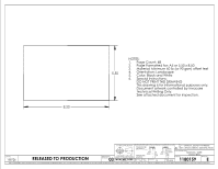
Page Count: 68
1.
Page Formatted for: A5 or 5.50 x 8.50
2.
Material: Minimum 60 lb (or 90 gsm) offset text
3.
Orientation: Landscape
4.
Color: Black and White
5.
Special Instructions:
6.
DO NOT PRINT THIS DRAWING
This drawing is for informational purposes only.
Document artwork controlled by Invacare
Technical Writing Only.
See attached document for inspection.
RELEASED TO PRODUCTION
E
1180159
03
158726
ELYRIA, OH.
INVACARE CORP.
SCALE:
DP
PRE-RELEASE
REVISION:
ALL DIMENSIONS ARE IN INCHES UNLESS OTHERWISE SPECIFIED
3rd ANGLE PROJECTION
ANSI/ASME Y14.5M-1994
UNLESS OTHERWISE SPECIFIED
C/N NO.
TOLERANCES:
INCHES
DECIMALS: ___
X =
N/A
.X =
.1
.XX =
. 02
.XXX =
.005
FRACTIONS:
_______
1/64
ANGLES:
__________
.5
METRIC
X =
3mm
.X =
.5mm
.XX =
.13mm
.XXX =
N/A
N/A
.5
3/2/2018
1:2
THIS IS THE PROPERTY OF INVACARE CORP. IT MUST NOT BE TRADED OR REPRODUCED IN ANY MANNER, NOR SHALL IT BE SUBMITTED TO OUTSIDE PARTIES FOR EXAMINATION WITHOUT OUR CONSENT. IT SHALL BE USED ONLY AS A MEANS OF REFERENCE TO DO WORK DESIGNED OR FURNISHED BY US. DO NOT SCALE THIS DRAWING.
A
= KEY CHARACTERISTIC IDENTIFICATION
TEMPLATE
SIZE:
DATE:
DRAWN BY:
1
= CRITICAL QUALITY ATTRIBUTE
REVISION
PART DESCRIPTION:
G5510 BED
MANUAL, USER
PART NO.