Kenwood TS-570D User Manual - Page 68
MCP AND TNC
 |
View all Kenwood TS-570D manuals
Add to My Manuals
Save this manual to your list of manuals |
Page 68 highlights
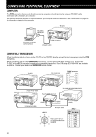
15 CONNECTING PERIPHERAL EQUIPMENT MCP AND TNC Use the ACC 2 connector to connect the input/output lines from a Terminal Node Controller (TNC) for Packet operation, a Multimode Communications Processor (MCP) for operation on Packet, PacTOR, AMTOR, G-TORTM, or FAX, or from a Clover interface. Also use the ACC 2 connector to connect SSTV and phone patch equipment. • Connect the TNC or MCP to the ACC 2 connector using a cable equipped with a 13-pin DIN plug. • Connecting the TNC or MCP to a personal computer or dumb terminal requires an RS-232C cable. Note: ◆ Do not share a single power supply between the transceiver and the TNC or MCP. Keep as wide a separation as possible between the transceiver and the computer as practical to reduce noise-pickup by the transceiver. ◆ The output voltage of Pin No. 6 (SMET) is not 0 V even when no signal is present. In addition, the output voltage differs between FM (approx. 2.8 ~ 3.8 V) and other modes (approx. 0.5 ~ 3.8 V). When connecting this pin to peripheral equipment such as a personal computer, the input impedance of that equipment must be higher than 1 MΩ. If you connect to equipment having lower impedance, the S-meter will not give accurate readings. Pin No. 1 2 3 Pin Name NC RTK ANO 4 GND 5 PSQ 6 SMET 7 NC 8 GND 9 PKS 10 NC 11 PKD 12 GND 13 SS Function Not connected RTTY key input AF output from receiver • Connect to TNC or MCP receive data pin for digital operation. • AF output level is independent of AF control setting. • AF output level can be changed via Menu No. 34. • Output impedance: 4.7 kΩ Shield for pin 3 Squelch control • Connect to TNC or MCP squelch control pin for digital operation. • Prevents the TNC from transmitting while the receiver squelch is open. • Squelch open: Low impedance • Squelch closed: High impedance S-meter output Not connected Chassis ground Transceiver PTT line control • Connect to TNC or MCP transmit/receive switching pin for digital operation. • Microphone audio input is muted when the transceiver is switched to the transmit mode. Not connected Microphone audio input • Connect to TNC or MCP transmit data pin for digital operation. Shield for pin 11 PTT control (in parallel with MIC jack) for connecting a footswitch or other external controller Black Red TNC/MCP power supply TNC/MCP Personal computer dumb terminal 62 TS-570 13 9 10 11 12 56 78 12 34 PS-53 ACC 2 Connector (Rear panel view)
-
 1
1 -
2
-
3
-
4
-
5
-
6
-
7
-
8
-
9
-
10
-
11
-
12
-
13
-
14
-
15
-
16
-
17
-
18
-
19
-
20
-
21
-
22
-
23
-
24
-
25
-
26
-
27
-
28
-
29
-
30
-
31
-
32
-
33
-
34
-
35
-
36
-
37
-
38
-
39
-
40
-
41
-
42
-
43
-
44
-
45
-
46
-
47
-
48
-
49
-
50
-
51
-
52
-
53
-
54
-
55
-
56
-
57
-
58
-
59
-
60
-
61
-
62
-
 63
63 -
 64
64 -
 65
65 -
 66
66 -
 67
67 -
 68
68 -
 69
69 -
 70
70 -
 71
71 -
 72
72 -
 73
73 -
74
-
75
-
76
-
77
-
78
-
79
-
80
-
81
-
82
-
83
-
84
-
85
-
86
-
87
-
88
-
89
 |
 |
