Invacare XLT Owners Manual - Page 53
Installing Seven Speed Shifter Cable
 |
View all Invacare XLT manuals
Add to My Manuals
Save this manual to your list of manuals |
Page 53 highlights
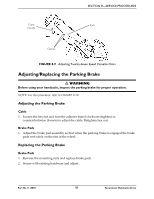
Top End XLT Gold ONLY Crank Assembly Tab Upper Threaded Post and Locknut SECTION 8-SERVICE PROCEDURES Socket Screws (One Located on Both Sides of the Handcycle Frame) Steering Dampener Top End Force ONLY Lower Threaded Post and Locknut Upper Threaded Post and Locknut Steering Dampener Handcycle Frame Dampener Clamp (Tab) Dampener Clamp (Tab) Crank Assembly Tab Handcycle Frame FIGURE 8.4 Installing/Removing/Adjusting the Steering Dampener - For Top End XLT Gold and Force Only Installing Seven Speed Shifter Cable NOTE: For this procedure, refer to FIGURE 8.5. NOTE: This procedure applies to the Top End XLT only. NOTE: The seven speed Shifter Cable runs from the right side of the front frame to its mounting position on the hand crank assembly. 1. Run the cable from the right‐side of the fork assembly to mounting position on the left side just below the hand crank assembly. Cable Hand Crank Assembly Extension Shifter 2. Attach the seven speed shifter to the hand crank assembly extension. 3. Secure with hardware provided. FIGURE 8.5 Installing Seven Speed Shifter Cable Part No 1114850 53 Recumbent Handcycle Series
-
 1
1 -
2
-
3
-
4
-
5
-
6
-
7
-
8
-
9
-
10
-
11
-
12
-
13
-
14
-
15
-
16
-
17
-
18
-
19
-
20
-
21
-
22
-
23
-
24
-
25
-
26
-
27
-
28
-
29
-
30
-
31
-
32
-
33
-
34
-
35
-
36
-
37
-
38
-
39
-
40
-
41
-
42
-
43
-
44
-
45
-
46
-
47
-
 48
48 -
 49
49 -
 50
50 -
 51
51 -
 52
52 -
 53
53 -
 54
54 -
 55
55 -
 56
56 -
 57
57 -
 58
58 -
59
-
60
-
61
-
62
-
63
-
64
-
65
-
66
-
67
-
68
-
69
-
70
-
71
-
72
-
73
-
74
-
75
-
76
 |
 |
