Invacare XLT Owners Manual - Page 39
Adjusting Back Angle - All Models Except XLT Gold and, Top End Force
 |
View all Invacare XLT manuals
Add to My Manuals
Save this manual to your list of manuals |
Page 39 highlights
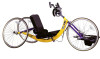
SECTION 6-RIDING POSITION Adjusting Back Angle - All Models Except XLT Gold and Top End Force NOTE: For this procedure, refer to FIGURE 6.9. 1. If installed activate parking brake. 2. Loosen, but DO NOT remove the four rear socket screws that secure the seat frame to the handcycle frame. NOTE: There are two socket screws on the right and left side of the handcycle. 3. Loosen, but DO NOT remove the hex bolts and locknuts that secure the two seat angle adjustment clamps to the rear seat supports. NOTE: There is one clamp on the right and left side of the handcycle. 4. Perform one of the following: • Increasing Back Angle ‐ While lifting up on the back support tubes, pull the seat upward to the desired position. • Decreasing Back Angle ‐ While pushing down on the back support tubes, push the seat down to the desired position. 5. Tighten the four socket screws that secure the seat frame to the handcycle frame securely. 6. Tighten the hex bolts and locknuts that secure the two seat angle adjustment clamps to the rear seat supports securely. Back Support Tube Seat Angle Adjustment Clamps Rear Socket Screws Handcycle Frame FIGURE 6.9 Adjusting Back Angle - All Models Except XLT Gold and Top End Force Part No 1114850 39 Recumbent Handcycle Series
-
 1
1 -
2
-
3
-
4
-
5
-
6
-
7
-
8
-
9
-
10
-
11
-
12
-
13
-
14
-
15
-
16
-
17
-
18
-
19
-
20
-
21
-
22
-
23
-
24
-
25
-
26
-
27
-
28
-
29
-
30
-
31
-
32
-
33
-
 34
34 -
 35
35 -
 36
36 -
 37
37 -
 38
38 -
 39
39 -
 40
40 -
 41
41 -
 42
42 -
 43
43 -
 44
44 -
45
-
46
-
47
-
48
-
49
-
50
-
51
-
52
-
53
-
54
-
55
-
56
-
57
-
58
-
59
-
60
-
61
-
62
-
63
-
64
-
65
-
66
-
67
-
68
-
69
-
70
-
71
-
72
-
73
-
74
-
75
-
76
 |
 |
