Invacare PATRIOT Owners Manual - Page 51
High Mount Wheel Lock Extension, Handle Installation
 |
View all Invacare PATRIOT manuals
Add to My Manuals
Save this manual to your list of manuals |
Page 51 highlights
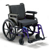
SECTION 9-ANTI-TIPPERS/WHEEL LOCKS ADJUSTING HIGH MOUNT WHEEL LOCKS NOTE: For this procedure, refer to FIGURE 9.7. 1. Make sure the wheel lock is disengaged from the rear wheels. 2. Loosen the socket screws that secure the wheel locks to the wheelchair frame. Socket Screws Wheelchair Frame 3. Measure the distance between the wheel lock shoe and the rear wheel. 4. Slide the wheel lock along the wheelchair until the measurement is between 5/32 and 5/16‐inches. Wheel Lock Rear Wheel 5. Tighten the wheel lock to the wheelchair frame. 6. Repeat this procedure for the opposite wheel lock. 7. Engage the wheel locks and push against the wheelchair to determine if the wheel locks engage the rear wheels enough to hold the wheelchair. 8. Repeat STEPS 1‐7 until the wheel locks engage the rear wheels enough to hold the wheelchair. Rear Wheel 5/32 to 5/16-inch Gap FIGURE 9.7 - ADJUSTING HIGH MOUNT WHEEL LOCKS HIGH MOUNT WHEEL LOCK EXTENSION HANDLE INSTALLATION NOTE: For this procedure, refer to FIGURE 9.8. NOTE: Wheel lock extension handles cannot be installed on high mount wheel locks already equipped with extension handles. 1. Remove and discard the existing rubber tip on the wheel lock handle (if applicable). 2. Remove the button screw, washer and locknut that secures the existing handle to the wheel lock assembly. 3. Attach the looped end of the elastic cord of the wheel lock extension handle over the spacer of the existing handle. 4. Reassemble the existing handle to the wheel lock with the button screw, washer and locknut to secure the cord around the spacer. NOTE: Cord is made of stretchable material and may be adjusted to a light or loose fit to meet the needs of the user. Part No 1088909 51 Patriot™
-
 1
1 -
2
-
3
-
4
-
5
-
6
-
7
-
8
-
9
-
10
-
11
-
12
-
13
-
14
-
15
-
16
-
17
-
18
-
19
-
20
-
21
-
22
-
23
-
24
-
25
-
26
-
27
-
28
-
29
-
30
-
31
-
32
-
33
-
34
-
35
-
36
-
37
-
38
-
39
-
40
-
41
-
42
-
43
-
44
-
45
-
 46
46 -
 47
47 -
 48
48 -
 49
49 -
 50
50 -
 51
51 -
 52
52 -
 53
53 -
 54
54 -
 55
55 -
 56
56 -
57
-
58
-
59
-
60
-
61
-
62
-
63
-
64
-
65
-
66
-
67
-
68
-
69
-
70
-
71
-
72
-
73
-
74
-
75
-
76
-
77
-
78
-
79
-
80
-
81
-
82
-
83
-
84
-
85
-
86
-
87
-
88
-
89
-
90
-
91
-
92
-
93
-
94
-
95
-
96
-
97
-
98
-
99
-
100
-
101
-
102
-
103
-
104
-
105
-
106
-
107
-
108
 |
 |
