| Section |
Page |
| 1088909E_English.pdf |
1 |
| Patriot™ |
1 |
| m Warning |
2 |
| DO NOT use this product or any available optional equipment without first completely reading and understanding these instructions and any additional instructional material such as owner’s manuals, service manuals or instruction sheets supplied with... |
2 |
| m Accessories warning |
2 |
| Invacare products are specifically designed and manufactured for use in conjunction with Invacare accessories. Accessories designed by other manufacturers have not been tested by Invacare and are not recommended for use with Invacare products. |
2 |
| NOTE: Updated versions of this manual are available on www.invacare.com. |
2 |
| table of contents |
3 |
| table of contents 3 |
3 |
| Register Your Product 5 |
3 |
| special notes 6 |
3 |
| Label Locations 7 |
3 |
| Typical Product Parameters 8 |
3 |
| section 1—General Guidelines 9 |
3 |
| Stability 9 |
3 |
| Anti-Tippers 9 |
3 |
| Repair and Service Information 10 |
3 |
| Operating Information 10 |
3 |
| Tire Pressure 11 |
3 |
| Weight Training 12 |
3 |
| Weight Limitation 12 |
3 |
| section 2—Safety/Handling of Wheelchairs 13 |
3 |
| Stability and Balance 13 |
3 |
| Coping with Everyday Obstacles 14 |
3 |
| A Note to Wheelchair Assistants 14 |
3 |
| Tipping 14 |
3 |
| Tipping - Curbs 14 |
3 |
| Stairways 16 |
3 |
| Transferring To and From Other Seats 17 |
3 |
| Percentage of Weight Distribution 17 |
3 |
| Reaching, Leaning and Bending - Forward 18 |
3 |
| Reaching, Bending - Backward 18 |
3 |
| Unfolding/Folding Sling Seat Model Wheelchairs 19 |
3 |
| Unfolding Sling Seat 19 |
3 |
| Folding Sling Seat 20 |
3 |
| Unfolding/Folding Solid Seat Model Wheelchairs 20 |
3 |
| section 3—Safety Inspection/troubleshooting 21 |
3 |
| Safety Inspection Checklists 21 |
3 |
| Inspect/Adjust Initially 21 |
3 |
| Inspect/Adjust Weekly 22 |
3 |
| Inspect/Adjust Monthly 22 |
3 |
| Inspect/Adjust Periodically 23 |
3 |
| Troubleshooting 24 |
3 |
| section 4—Maintenance/transporting 25 |
3 |
| Maintenance Safety Precautions 25 |
4 |
| Suggested Maintenance Procedures 25 |
4 |
| Transporting the Invacare Patriot 26 |
4 |
| section 5—Front Riggings 27 |
4 |
| Installing/Removing Swingaway Footrest 27 |
4 |
| Installing Swingaway Footrest 27 |
4 |
| Removing Swingaway Footrest 28 |
4 |
| Adjusting Swingaway Footrest Height 28 |
4 |
| Removing/Installing Heel Loops 28 |
4 |
| Removing Heel Loops 28 |
4 |
| Installing Heel Loops 29 |
4 |
| Installing/Removing Elevating Legrest 29 |
4 |
| Installing Elevating Legrest 29 |
4 |
| Removing Elevating Legrest 30 |
4 |
| Adjusting Elevating Legrest/Calfpad Assembly 30 |
4 |
| Adjusting the Legrest 30 |
4 |
| Adjusting the Calfpad 30 |
4 |
| Installing Adjustable Angle Flip-Up Footplates 31 |
4 |
| Adjusting Adjustable Angle Flip-Up Footplates 31 |
4 |
| Depth Adjustment 32 |
4 |
| Angle Adjustment 32 |
4 |
| section 6—Arms 33 |
4 |
| Adjusting/Using Armrest 33 |
4 |
| Adjusting Armrest Height 33 |
4 |
| Using Armrest 34 |
4 |
| Removing/Installing Flip Back Armrest 34 |
4 |
| Removing Flip Back Armrest 34 |
4 |
| Installing Flip Back Armrest 34 |
4 |
| section 7—seat/Back 36 |
4 |
| Removing/Installing Seat Upholstery 36 |
4 |
| Removing Seat Upholstery 36 |
4 |
| Installing Seat Upholstery 36 |
4 |
| Removing/Installing Back Upholstery 37 |
4 |
| Removing Back Upholstery 37 |
4 |
| Installing Back Upholstery 37 |
4 |
| Adjusting Adjustable Tension Back Upholstery 38 |
4 |
| Installing/Removing Seat Positioning Strap 39 |
4 |
| Installing/Removing Chest Positioning Strap 40 |
4 |
| section 8—Rear wheels/front casters 41 |
4 |
| Removing/Installing Rear Wheels 41 |
5 |
| Permanent Axles 41 |
5 |
| Quick-Release Axles 42 |
5 |
| Adjusting Quick-Release Axles 43 |
5 |
| Replacing Handrims 43 |
5 |
| Replacing/Repairing Rear Wheel Tire/Tube 44 |
5 |
| Replacing/Repairing Front Caster Tire/Tube 44 |
5 |
| Front Caster Mounting/Seat-to-floor Height 44 |
5 |
| Adjusting Forks 45 |
5 |
| section 9—anti-Tippers/Wheel locks 46 |
5 |
| Installing/Adjusting Anti-Tippers 46 |
5 |
| Installing Anti-Tippers 46 |
5 |
| Adjusting Anti-Tippers 47 |
5 |
| Using/Adjusting Wheel Locks (Push-to-Lock/Pull-to-Lock) 48 |
5 |
| Using Wheel Locks 48 |
5 |
| Adjusting Wheel Locks 49 |
5 |
| Installing Wheel Lock Shoe Spacers 49 |
5 |
| Using/Adjusting High Mount Wheel Locks (Push-to-Lock/Pull-to-Lock) 50 |
5 |
| Using High Mount Wheel Locks 50 |
5 |
| Adjusting High Mount Wheel Locks 51 |
5 |
| High Mount Wheel Lock Extension Handle Installation 51 |
5 |
| LIMITED WARRANTY 53 |
5 |
| Register Your Product |
5 |
| The benefits of registering include: |
5 |
| 1. Safeguarding your investment. |
5 |
| 2. Ensuring long-term maintenance and servicing of your product. |
5 |
| 3. Receiving updates with product information, maintenance tips and industry news. |
5 |
| Register online at warranty.invacare.com |
5 |
| Please have your model number and purchase date available to complete your registration. |
5 |
| Any registration information you submit will only be used by Invacare Corporation and protected as required by applicable laws and regulations. |
5 |
| special notes |
6 |
| Signal words are used in this manual and apply to hazards or unsafe practices which could result in personal injury or property damage. Refer to the table below for definitions of the signal words. |
6 |
| Signal Word |
6 |
| meaning |
6 |
| Danger indicates an imminently hazardous situation which, if not avoided, will result in death or serious injury. |
6 |
| Warning indicates a potentially hazardous situation which, if not avoided, could result in death or serious injury. |
6 |
| Caution indicates a potentially hazardous situation which, if not avoided, may result in property damage or minor injury or both. |
6 |
| notice |
6 |
| THE INFORMATION CONTAINED IN THIS DOCUMENT IS SUBJECT TO CHANGE WITHOUT NOTICE. |
6 |
| WHEELCHAIR USER |
6 |
| As a manufacturer of wheelchairs, Invacare endeavors to supply a wide variety of wheelchairs to meet many needs of the end user. However, final selection of the type of wheelchair to be used by an individual rests solely with the user and his/her hea... |
6 |
| WHEELCHAIR TIE-DOWN RESTRAINTS AND SEAT Positioning Strap |
6 |
| Invacare recommends that wheelchair users NOT be transported in vehicles of any kind while in wheelchairs. As of this date, the Department of Transportation has not approved any tie-down systems for transportation of a user while in a wheelchair, in ... |
6 |
| It is Invacare’s position that users of wheelchairs should be transferred into appropriate seating in vehicles for transportation and use be made of the restraints made available by the auto industry. Invacare cannot and does not recommend any whee... |
6 |
| SEAT POSITIONING STRAP |
6 |
| Always wear your seat positioning strap. |
6 |
| The seat positioning strap is a positioning strap only. It is not designed for use as a safety device withstanding high stress loads such as auto or aircraft safety belts. If signs of wear appear, strap MUST be replaced immediately. |
6 |
| With regards to seat/chest positioning straps - it is the obligation of the DME dealer, therapists and other healthcare professionals to determine if a seat/chest positioning strap is required to ensure the safe operation of this equipment by the use... |
6 |
| Label Locations |
7 |
| Models with adjustable angle back only |
7 |
| Typical Product Parameters |
8 |
| patriot |
8 |
| oVERALL WIDTH: |
8 |
| 21½, 23½-25½, 27½ inches |
8 |
| overall depth (with riggings) |
8 |
| 43 or 45 inches |
8 |
| seat width: |
8 |
| 14, 16, 17, 18, or 20 inches |
8 |
| seat Depth: |
8 |
| 16 or 18 inches |
8 |
| seat-to-floor (adult/hemi): |
8 |
| 15½ to 19½ inches - in 1-inch increments |
8 |
| back style: |
8 |
| Adjustable - in 1-inch increments |
8 |
| Adjustable Angle - 85° to 110° in 5° increments |
8 |
| back height: |
8 |
| 15-19 inches (Standard on both) |
8 |
| 20 inch (Optional Back Cane) |
8 |
| Arm styles: |
8 |
| Swing Back (Standard) |
8 |
| Space Saver |
8 |
| Desk Length (Standard) |
8 |
| Full Length |
8 |
| Fixed Height (Standard) |
8 |
| Adjustable Height |
8 |
| front riggings: |
8 |
| Swingaway Footrests |
8 |
| Elevating Legrests |
8 |
| rear axle: |
8 |
| Permanent (Standard) |
8 |
| Quick-Release |
8 |
| Rear Wheels: |
8 |
| 20, 22 and 24 inch Composite |
8 |
| Urethane |
8 |
| Pneumatic |
8 |
| Pneumatic-Flat Free Insert |
8 |
| (Standard: 24-inch Composite Urethane) |
8 |
| handrims: |
8 |
| Composite Projection |
8 |
| Composite Non-Projection (Standard) |
8 |
| Aluminum Projection |
8 |
| Aluminum Non-Projection |
8 |
| Wheel locks: |
8 |
| Toggle Lock - Push or Pull |
8 |
| caster size: |
8 |
| 6x1 inch Urethane |
8 |
| 8x1 inch Urethane (Standard) |
8 |
| 8x1¼ inch Pneumatic or Pneumatic-Flat Free Insert |
8 |
| Upholstery: |
8 |
| U240 Black Nylon |
8 |
| weight: |
8 |
| Patriot - 29 lbs |
8 |
| Weight Capacity |
8 |
| 250 lbs |
8 |
| shipping weight (approximate): |
8 |
| Patriot - 39.5lbs* |
8 |
| *NOTE: 16x16 inch Seat Frame with packaging. |
8 |
| NOTE: Invacare recommends that rear seat-to-floor heights be at least 3/8-inch shorter than front seat-to-floor height. The seat-to-floor heights are based on urethane tires. If wheelchair is equipped with pneumatic tires or pneumatic tires with flat... |
8 |
| Section 1— General Guidelines |
9 |
| m warning |
9 |
| SECTION 1 - GENERAL GUIDELINES contains important information for the safe operation and use of this product. |
9 |
| Stability |
9 |
| The seat depth, back height/angle, seat angle, size/position of the front casters, seat-to- floor angle, position of the rear wheels, correct anti-tipper as well as the end user’s disability or end user’s physical condition and capabilities direc... |
9 |
| NOTE: When changes to the left hand column occur, follow across the chart and refer to the X procedure to maintain the proper stability, safety and handling of the wheelchair. |
9 |
| seat depth |
9 |
| Back height |
9 |
| back angle |
9 |
| seat angle |
9 |
| caster size |
9 |
| caster position |
9 |
| wheel size |
9 |
| wheel position |
9 |
| user condition |
9 |
| Seat-to-floor heights have specific positions depending on rear wheel size, rear wheel position, front caster size/position and seat-to-floor angle. These adjustments MUST be performed by a qualified technician. |
9 |
| Anti-Tippers |
9 |
| Anti-tippers are specific to the different seat-to-floor angles and/or seat-to-floor heights. Refer to the chart in Installing/Adjusting Anti-Tippers on page 46 of this manual for correct usage and adjustment. If these requirements cannot be achieved... |
9 |
| Anti-tippers MUST BE used at all times. When outdoors on wet, soft ground or on gravel surfaces, anti-tippers may not provide the same level of protection against tip over. Extra caution must be observed when traversing such surfaces. |
10 |
| Seat-to-floor angle of 0° or 3°: (You may order with or without the anti-tippers), Invacare strongly recommends ordering the anti-tippers as a safeguard for the wheelchair user. |
10 |
| Seat-to-floor angle of 6°: If changing the seat-to-floor angle to 6°, anti-tippers MUST be ordered and installed. |
10 |
| Seat-to-floor height (which includes seat-to-floor angle): If changing the seat-to-floor height with or without a change to seat-to-floor angle, the correct anti-tippers MUST be ordered to maintain a 1½ to 2-inch ground clearance. |
10 |
| Repair and Service Information |
10 |
| Unless otherwise noted, all service and adjustments should be performed while the wheelchair is unoccupied. |
10 |
| Operating Information |
10 |
| DO determine and establish your particular safety limits, practice bending, reaching and transferring activities in several combinations in the presence of a qualified healthcare professional BEFORE attempting active use of the wheelchair. |
10 |
| DO NOT attempt to reach objects if you have to move forward in the seat. |
10 |
| DO NOT attempt to reach objects if you have to pick them up from the floor by reaching down between your knees. |
10 |
| DO NOT lean over the top of the back upholstery to reach objects from behind as this may cause the wheelchair and/or seating system to tip over. |
10 |
| DO NOT shift your weight or sitting position toward direction you are reaching as the wheelchair and/or seating system may tip over. |
10 |
| DO NOT tip the wheelchair without assistance. |
10 |
| DO NOT use an escalator to move a wheelchair between floors. Serious bodily injury may occur. |
10 |
| DO NOT attempt to stop a moving wheelchair with the wheel locks. Wheel locks are NOT brakes. |
10 |
| Before attempting to transfer in or out of the wheelchair, every precaution should be taken to reduce the gap distance. Turn both casters parallel to the object you are transferring onto. When transferring to and from the wheelchair, ALWAYS engage bo... |
10 |
| DO NOT operate on roads, streets or highways. |
10 |
| DO NOT go up or down ramps or traverse slopes greater than 9°. |
10 |
| DO NOT attempt to move up or down an incline with a water, ice or oil film. |
10 |
| DO NOT attempt to ride over curbs or obstacles. Doing so may cause your wheelchair to tip over and cause bodily harm to the user and/or assistant or damage to the wheelchair. |
11 |
| DO NOT attempt to lift the wheelchair by any removable (detachable) parts. Lifting by means of any removable (detachable) parts of a wheelchair may result in injury to the user and/or assistant or damage to the wheelchair. |
11 |
| DO NOT stand on the frame of the wheelchair. |
11 |
| DO NOT overtighten hardware attaching to the frame. This could cause damage to the frame tubing. |
11 |
| ALWAYS keep hands and fingers clear of moving parts to avoid injury. |
11 |
| NEVER leave an unoccupied wheelchair on an incline. |
11 |
| DO NOT use the footplates as a platform. When getting in or out of the wheelchair, make sure that the footplates are in the upward position or swing footrests towards the outside of the wheelchair. |
11 |
| The seat positioning strap is a positioning strap only. It is not designed for use as a safety device withstanding high stress loads such as auto or aircraft safety belts. If signs of wear appear, strap must be replaced immediately. |
11 |
| ALWAYS wear your seat and/or chest positioning strap. Inasmuch as the seat and/or chest positioning strap is an option on this wheelchair (you may order with or without the seat and/or chest positioning strap), Invacare strongly recommends ordering t... |
11 |
| ALWAYS engage both wheel locks and reduce the gap distance BEFORE transferring to and from the wheelchair. Turn all casters parallel to the object you are transferring onto. |
11 |
| ALWAYS verify that hand grips on the rear cane are secure PRIOR to use when an assistant is used to propel or lift the chair. Check for any signs of looseness or deterioration and if found, contact a qualified technician. DO NOT attempt to move the w... |
11 |
| ALWAYS use handrims for self-propulsion. Inasmuch as the HANDRIMS are an option on this wheelchair (you may order with or without the handrims), Invacare strongly recommends ordering the handrims as an additional safeguard for the wheelchair user. |
11 |
| Tire Pressure |
11 |
| DO NOT use your wheelchair unless it has the proper tire pressure (p.s.i.). DO NOT overinflate the tires. Failure to follow these suggestions may cause the tire to explode and cause bodily harm. The recommended tire pressure is listed on the side wal... |
11 |
| Replacement of a pneumatic tire or tube MUST be performed by a qualified technician. |
11 |
| Weight Training |
12 |
| Invacare DOES NOT recommend the use of its wheelchairs as a weight training apparatus. Invacare wheelchairs have NOT been designed or tested as a seat for any kind of weight training. If occupant uses said wheelchair as a weight training apparatus, I... |
12 |
| Weight Limitation |
12 |
| The Patriot wheelchair has a weight limitation of 250 lbs (114 kg). |
12 |
| Section 2— Safety/Handling of Wheelchairs |
13 |
| “Safety and Handling” of the wheelchair requires the close attention of the wheelchair user as well as the assistant. This manual points out the most common procedures and techniques involved in the safe operation and maintenance of the wheelchai... |
13 |
| Use this information only as a “basic” guide. The techniques that are discussed on the following pages have been used successfully by many. |
13 |
| Individual wheelchair users often develop skills to deal with daily living activities that may differ from those described in this manual. Invacare recognizes and encourages each individual to try what works best for him/her in overcoming architectur... |
13 |
| Stability and Balance |
13 |
| m WARNING |
13 |
| ALWAYS wear your seat positioning strap. Inasmuch as the seat positioning strap is an option on this wheelchair (You may order with or without the seat positioning strap), Invacare strongly recommends ordering the seat positioning strap as an additio... |
13 |
| The seat positioning strap is a positioning strap only. It is not designed for use as a safety device withstanding high stress loads such as auto or aircraft safety belts. If signs of wear appear, strap must be replaced immediately. |
13 |
| DO NOT climb, go up, or down ramps or traverse slopes greater than 9°. |
13 |
| Invacare strongly recommends proceeding down ramps or slopes slowly to avoid hard braking or sudden stops. |
13 |
| DO NOT leave elevating legrests in the fully extended position when proceeding down ramps or slopes. |
13 |
| Be aware that carrying heavy objects on your lap while occupying the wheelchair may adversely affect the stability of the wheelchair, resulting in serious bodily injury to the user, damage to the wheelchair and surrounding property. |
13 |
| This wheelchair has been designed to accommodate one individual. If more than one individual occupies the wheelchair this may adversely affect the stability of the wheelchair, resulting in serious bodily injury to the user and passenger and damage th... |
13 |
| To assure stability and proper operation of your wheelchair, you must at all times wear your seat restraint and maintain proper balance. Your wheelchair has been designed to remain upright and stable during normal daily activities as long as you do n... |
14 |
| Virtually all activities which involve movement in the wheelchair have an effect on the center of gravity. Invacare recommends using seat positioning straps for additional safety while involved in activities that shift your weight. |
14 |
| DO NOT lean forward out of the wheelchair any further than the length of the armrests. Make sure the casters are pointing in the forward position whenever you lean forward. This can be achieved by advancing the wheelchair and then reversing it in a s... |
14 |
| Coping with Everyday Obstacles |
14 |
| Coping with the irritation of everyday obstacles can be alleviated somewhat by learning how to manage your wheelchair. Keep in mind your center of gravity to maintain stability and balance. |
14 |
| A Note to Wheelchair Assistants |
14 |
| When assistance to the wheelchair user is required, remember to use good body mechanics. Keep your back straight and bend your knees whenever tilting the wheelchair or traversing curbs, or other impediments. |
14 |
| Also, be aware of detachable parts such as arms or legrests. These must NEVER be used to move the wheelchair or as lifting supports, as they may be inadvertently released, resulting in possible injury to the user and/or assistant(s). |
14 |
| When learning a new assistance technique, have an experienced assistant help you before attempting it alone. |
14 |
| Tipping |
14 |
| m warning |
14 |
| DO NOT tip the wheelchair without assistance. |
14 |
| When tipping the wheelchair, an assistant should grasp the back of the wheelchair on a non-removable (non-detachable) part. Inform the wheelchair occupant before tipping the wheelchair and remind him/her to lean back. Be sure the occupant’s feet an... |
14 |
| Tipping - Curbs |
14 |
| After mastering the techniques of tipping the wheelchair, use this procedure to tackle curbs, short stairs, etc. |
14 |
| Method 1 - Wheelchair with Step Tubes |
14 |
| NOTE: For this procedure, refer to FIGURE 2.1. |
14 |
| Apply a continuous downward motion until the balance point is achieved and the front casters clear the curb. At this point, the assistant will feel a difference in the weight distribution. |
15 |
| Roll the wheelchair forward and slowly lower the wheelchair in one continuous movement onto the sidewalk. |
15 |
| m warning |
15 |
| DO NOT let the wheelchair drop the last few inches to the ground. This could result in injury to the occupant. |
15 |
| Push the wheelchair forward until the rear wheels roll up and over the curb. |
15 |
| FIGURE 2.1 - Method 1 - Wheelchair with Step Tubes |
15 |
| Method 2 - Wheelchair without Step Tubes |
15 |
| NOTE: For this procedure, refer to FIGURE 2.2. |
15 |
| FIGURE 2.2 - Method 2 - Wheelchair without Step Tubes |
15 |
| Stairways |
16 |
| m WARNING |
16 |
| DO NOT attempt to lift a wheelchair by lifting on any removable (detachable) parts. Lifting by means of any removable (detachable) parts of a wheelchair may result in injury to the user or damage to the wheelchair. |
16 |
| Extreme caution is advised when it is necessary to move an occupied wheelchair up or down the stairs. Invacare recommends using two assistants and making thorough preparations. Make sure to use only secure, non-detachable parts for hand-held supports. |
16 |
| ALWAYS wear your seat positioning strap. Inasmuch as the seat positioning strap is an option on this wheelchair (You may order with or without the seat restraint), Invacare strongly recommends ordering the seat restraint as an additional safeguard fo... |
16 |
| The seat positioning strap is a positioning strap only. It is not designed for use as a safety device withstanding high stress loads such as auto or aircraft safety belts. If signs of wear appear, strap MUST be replaced immediately. |
16 |
| Follow this procedure for moving the wheelchair between floors when an elevator is NOT available: |
16 |
| 1. Turn the anti-tippers so they are facing UP. |
16 |
| 2. After the wheelchair has been tilted back to the balance point, one assistant (in the rear) backs the wheelchair up against the first step, while securely grasping a non- removable (non-detachable) part of the wheelchair for leverage. |
16 |
| 3. The second assistant, with a firm hold on a non-detachable part of the framework, lifts the wheelchair up and over the stair and steadies the wheelchair as the first assistant places one foot on the next stair and repeats STEP 1. |
16 |
| 4. The wheelchair should not be lowered until the last stair has been negotiated and the wheelchair has been rolled away from the stairway. |
16 |
| 5. Turn the anti-tippers so they are facing DOWN. |
16 |
| m warning |
16 |
| DO NOT use an escalator to move a wheelchair between floors. Serious bodily injury may occur. |
16 |
| Transferring To and From Other Seats |
17 |
| m WARNING |
17 |
| BEFORE attempting to transfer in or out of the wheelchair, every precaution should be taken to reduce the gap distance. Align both casters parallel with the object you are transferring onto. Also be certain the wheel locks are engaged to help prevent... |
17 |
| CAUTION |
17 |
| When transferring, position yourself as far back as possible in the seat. This will prevent damaged upholstery and the possibility of the wheelchair tipping forward. |
17 |
| 1. Position the wheelchair as close as possible along side the seat to which you are transferring, with the front casters parallel to it. |
17 |
| 2. Engage wheel locks. |
17 |
| 3. Remove or flip back armrests. |
17 |
| 4. Shift body weight into seat with transfer. |
17 |
| maximum gap distance |
17 |
| FIGURE 2.3 - Transferring To and From Other Seats |
17 |
| Percentage of Weight Distribution |
17 |
| m WARNING |
17 |
| DO NOT attempt to reach objects if you have to move forward in the seat or pick them up from the floor by reaching down between your knees. |
17 |
| The seat depth, back height/angle, seat angle, size/position of the front casters, seat- to-floor angle, position of the rear wheels, correct anti-tipper as well as the end user’s disability or end user’s physical condition and capabilities direc... |
17 |
| NOTE: For this procedure, refer to FIGURE 2.4. |
17 |
| FIGURE 2.4 - Percentage of Weight Distribution |
18 |
| Reaching, Leaning and Bending - Forward |
18 |
| Proper positioning is essential for your safety. When reaching, leaning, bending forward, it is important to use the front casters as a tool to maintain stability and balance. |
18 |
| m warning |
18 |
| FIGURE 2.5 - Reaching, Leaning and Bending - Forward |
18 |
| Reaching, Bending - Backward |
18 |
| m WARNING |
18 |
| DO NOT lean over the top of the back upholstery. This will change your center of gravity and may cause you to tip over. |
18 |
| Keep hands and fingers clear of moving parts to avoid injury. |
18 |
| NOTE: For this procedure, refer to FIGURE 2.6 |
18 |
| FIGURE 2.6 - Reaching, Bending - Backward |
19 |
| Unfolding/Folding Sling Seat Model Wheelchairs |
19 |
| m warning |
19 |
| DO NOT sit or transfer into the wheelchair unless it is fully open and the seat rails are fully seated into the side frame H-blocks. |
19 |
| Unfolding Sling Seat |
19 |
| 1. Grasp the push closest to you. |
19 |
| 2. Tilt the wheelchair towards you (raising the opposite wheel and caster off the ground/floor). |
19 |
| 3. Push downward on the seat rail closest to you where the seat upholstery is attached until the wheelchair is fully open. |
19 |
| 4. Engage both wheel locks, open the footrest/legrest for clearance and transfer into the wheelchair. Refer to Transferring To and From Other Seats on page 17. |
19 |
| FIGURE 2.7 - Unfolding Sling Seat |
19 |
| Folding Sling Seat |
20 |
| 1. Swing footrest/legrest in locked position to the front of the wheelchair. |
20 |
| 2. Pivot footplates upward to vertical position. |
20 |
| 3. With both hands, grasp the middle of the seat upholstery at the front and back edge and lift up. Or, tilt the wheelchair to one side and close by the push handles. |
20 |
| FIGURE 2.8 - Folding Sling Seat |
20 |
| Unfolding/Folding Solid Seat Model Wheelchairs |
20 |
| NOTE: For this procedure, refer to FIGURE 2.9. |
20 |
| 1. From behind the wheelchair, grasp the right hand edge of the solid seat. |
20 |
| 2. Raise the seat to the hinged side. |
20 |
| 3. Swing footrest/legrest in locked position to the front of the wheelchair. |
20 |
| 4. Pivot footplates upward to vertical position. |
20 |
| 5. With both hands, grasp the middle of the seat upholstery at the front and back edge and lift up or tilt the wheelchair to one side and close by the push handles. |
20 |
| FIGURE 2.9 - Unfolding/Folding Solid Seat Model Wheelchairs |
20 |
| Section 3— Safety Inspection/ troubleshooting |
21 |
| NOTE: Twice a year, take your wheelchair to a qualified dealer for a thorough inspection and servicing. Regular cleaning will reveal loose or worn parts and enhance the smooth operation of your wheelchair. To operate properly and safely, your wheelch... |
21 |
| Safety Inspection Checklists |
21 |
| Initial adjustments should be made to suit the personal body structure needs and preferences of the user. Thereafter follow these maintenance procedures: |
21 |
| Inspect/Adjust Initially |
21 |
| Wheelchair rolls straight (no excessive drag or pull to one side). |
21 |
| Ensure all hardware is tight. |
21 |
| No bent or protruding metal on clothing guards. |
21 |
| All fasteners on clothing guards are secure. |
21 |
| Arms are secure but easy to release and adjustment levers engage properly. |
21 |
| Adjustable height arms operate and lock securely. |
21 |
| Armrest pad sits flush against arm tube. |
21 |
| Seat and/or back upholstery have no rips. |
21 |
| Inspect adjustable angle back attaching hardware is securely tightened. |
21 |
| Ensure hand grips are not loose. |
21 |
| Sealed bearings and axle nut tension are correct. |
21 |
| No excessive side movement or binding when rear wheels are lifted and spun. |
21 |
| Quick-release axles lock properly. |
21 |
| Inspect handrims for signs of rough edges or peeling finish. |
21 |
| Inspect for broken spokes. |
21 |
| Wheel/fork assembly has proper tension when caster is spun. Caster should come to a gradual stop. |
21 |
| caution |
21 |
| As with any vehicle, the wheels/casters and tires should be checked periodically for cracks, flat spots and wear, and should be replaced. |
21 |
| Loosen/tighten locknut if wheel wobbles noticeably or binds to a stop. |
21 |
| Wheel bearings are clean and free of moisture. |
22 |
| Ensure all caster/wheel/fork/headtube fasteners are secure. |
22 |
| Wheel locks do not interfere with tires when rolling. |
22 |
| Wheel lock pivot point are free of wear and looseness. |
22 |
| Wheel locks are easy to engage. |
22 |
| Inspect tires/casters for flat spots and wear. |
22 |
| Check pneumatic tires for proper inflation (recommended tire pressure is listed on the side wall of the tire). |
22 |
| m warning |
22 |
| do not use WD-40®, 3-in-1 Oil®, or other penetrating lubricants on quick-release axles. Otherwise, binding and/or damage to the wheelchair may occur. |
22 |
| Clean quick-release axles with a Teflon® lubricant. |
22 |
| Ensure axles are free from dirt, lint, etc. |
22 |
| Ensure roller bearings are free from dirt, lint, etc. |
22 |
| Adjust wheel locks as tires wear. |
22 |
| Clean and wax all parts. |
22 |
| Clean upholstery and armrests. |
22 |
| Inspect/Adjust Weekly |
22 |
| Wheelchair rolls straight (no excessive drag or pull to one side). |
22 |
| Quick-release axles lock properly. |
22 |
| Inspect for broken spokes. |
22 |
| Wheel/fork assembly has proper tension when caster is spun. Caster should come to a gradual stop. |
22 |
| Inspect tires/casters for flat spots and wear. |
22 |
| Check pneumatic tires for proper inflation (recommended tire pressure is listed on the side wall of the tire). |
22 |
| Inspect/Adjust Monthly |
22 |
| Inspect seat positioning strap for any signs of wear. Ensure buckle latches. Verify hardware that attaches strap to frame is secure and undamaged. Replace if necessary. |
22 |
| Loosen/tighten locknut if wheel wobbles noticeably or binds to a stop. |
22 |
| Wheel bearings are clean and free of moisture. |
22 |
| Wheel locks do not interfere with tires when rolling. |
22 |
| Wheel lock pivot point are free of wear and looseness. |
22 |
| Ensure all caster/wheel/fork/headtube fasteners are secure. |
23 |
| Ensure all hardware is tight. |
23 |
| Ensure hand grips are not loose. |
23 |
| Inspect/Adjust Periodically |
23 |
| Wheelchair rolls straight (no excessive drag or pull to one side). |
23 |
| Arms are secure but easy to release and adjustment levers engage properly. |
23 |
| Adjustable height arms operate and lock securely. |
23 |
| Armrest pad sits flush against arm tube. |
23 |
| No bent or protruding metal on clothing guards. |
23 |
| All fasteners on clothing guards are secure. |
23 |
| Seat and/or back upholstery have no rips. |
23 |
| Inspect adjustable angle back attaching hardware is securely tightened. |
23 |
| No excessive side movement or binding when rear wheels are lifted and spun. |
23 |
| Inspect handrims for signs of rough edges or peeling finish. |
23 |
| Inspect tires/casters for flat spots and wear. |
23 |
| Check pneumatic tires for proper inflation (recommended tire pressure is listed on the side wall of the tire). |
23 |
| Wheel lock pivot point are free of wear and looseness. |
23 |
| Clean upholstery and armrests. |
23 |
| Sealed bearings and axle nut tension are correct. |
23 |
| Wheel/fork assembly has proper tension when caster is spun. Caster should come to a gradual stop. |
23 |
| Loosen/tighten locknut if wheel wobbles noticeably or binds to a stop. |
23 |
| Wheel bearings are clean and free of moisture. |
23 |
| Wheel locks are easy to engage. |
23 |
| Clean quick-release axles with a Teflon® lubricant. |
23 |
| Ensure axles are free from dirt, lint, etc. |
23 |
| Ensure roller bearings are free from dirt, lint, etc. |
23 |
| Adjust wheel locks as tires wear. |
23 |
| Clean and wax all parts. |
23 |
| Check that all labels are present and legible. Replace if necessary. |
23 |
| Ensure that casters are free of debris. |
23 |
| Troubleshooting |
24 |
| solutions |
24 |
| If pneumatic tires, check for correct and equal pressure. |
24 |
| Check for loose stem nuts/bolts. |
24 |
| Check caster angle adjustment. |
24 |
| Check that casters contact ground at the same time. |
24 |
| Section 4— Maintenance/ transporting |
25 |
| Maintenance Safety Precautions |
25 |
| m warning |
25 |
| After ANY adjustments, repair or service and BEFORE use, make sure all attaching hardware is tightened securely - otherwise injury or damage may occur. |
25 |
| caution |
25 |
| DO NOT overtighten hardware attaching to the frame. This could cause damage to the frame tubing. |
25 |
| Suggested Maintenance Procedures |
25 |
| 1. Before using your Patriot, make sure all nuts and bolts are tight. Check all parts for damage or wear and replace. Check all parts for proper adjustment. |
25 |
| 2. Keep quick-release axles free of dirt and lint to ensure positive locking and proper operation. Refer to Refer to Adjusting Quick-Release Axles on page 43. |
25 |
| m warning |
25 |
| DO NOT use the wheelchair unless it has the proper tire pressure (p.s.i.). DO NOT overinflate the tires. Failure to follow these suggestions may cause the tire to explode and cause bodily harm. |
25 |
| 3. If tires are pneumatic, recommended tire pressure is listed on the side wall of the tire. |
25 |
| 4. The wheels and tires should be checked periodically for cracks and wear, and should be replaced when necessary by a qualified technician. |
25 |
| 5. Periodically check handrims to ensure they are secured to the rear wheels. Refer to Refer to Replacing Handrims on page 43. |
25 |
| 6. Periodically adjust wheel locks in correlation to tire wear. Refer to Using/Adjusting Wheel Locks (Push-to-Lock/Pull-to-Lock) on page 48 or Refer to Using/Adjusting High Mount Wheel Locks (Push-to-Lock/Pull-to-Lock) on page 50. |
25 |
| 7. Periodically check front caster wheel bearings to make sure they are clean and free from moisture. Use a Teflon® lubricant if necessary. |
25 |
| 8. Check upholstery for sagging, rips or tears. |
25 |
| Transporting the Invacare Patriot |
26 |
| 1. Remove the seating system. Refer to the seating system Owner’s Manual for installation and removal of the seating system. |
26 |
| 2. Remove the footrests. Refer to Installing/Removing Swingaway Footrest on page 27. |
26 |
| 3. Remove the rear wheels. Refer to Removing/Installing Rear Wheels on page 41. |
26 |
| 4. Remove the armrests. Refer to Removing/Installing Flip Back Armrest on page 34. |
26 |
| 5. Remove the anti-tippers. Refer to Installing/Adjusting Anti-Tippers on page 46. |
26 |
| Section 5— Front Riggings |
27 |
| m Warning |
27 |
| After ANY adjustments, repair or service and before use, make sure all attaching hardware is tightened securely - otherwise injury or damage may occur. |
27 |
| Installing/Removing Swingaway Footrest |
27 |
| NOTE: For this procedure, refer to FIGURE 5.1. |
27 |
| NOTE: 70° front riggings require the casters to be in the trailing position. Repositioning casters MUST be performed by a qualified technician. |
27 |
| Installing Swingaway Footrest |
27 |
| 1. Turn the footrest to the side (open footplate is perpendicular to the wheelchair). |
27 |
| 2. Insert the footrest assembly mounting pin into the mounting tube of the wheelchair frame. |
27 |
| 3. Rotate the footrest towards the inside of the wheelchair until it locks into place. |
27 |
| 4. Repeat STEPS 1-3 for the other footrest assembly. |
27 |
| 5. Adjust the footrest height, if necessary. Refer to Adjusting Swingaway Footrest Height on page 28 of the manual. |
27 |
| Swingaway Footrest Assembly |
27 |
| FIGURE 5.1 - Installing/ Removing Swingaway Footrest |
27 |
| Removing Swingaway Footrest |
28 |
| 1. Push the footrest release lever inward while rotating the footrest outward. |
28 |
| 2. Lift the footrest assembly out of the mounting pin of the wheelchair frame. |
28 |
| 3. Repeat STEPS 1-2 for opposite side, if necessary. |
28 |
| Adjusting Swingaway Footrest Height |
28 |
| 1. Remove the footrest from the wheelchair. Refer to Installing/Removing Swingaway Footrest on page 27. |
28 |
| 2. Remove the hex screw and coved spacer and slide the footrest up or down on its mounting tube until the desired footrest height is achieved. |
28 |
| 3. Reassemble the hex screw and coved spacer through the footrest upper support and mounting tube as shown in FIGURE 5.2. |
28 |
| 4. Securely tighten the hex screw and coved spacer. |
28 |
| 5. Install the footrest assembly onto the wheelchair. Refer to Installing/ Removing Swingaway Footrest on page 27. |
28 |
| 6. Repeat STEPS 1-5 for the opposite side of the wheelchair, if necessary. |
28 |
| Hex Screw |
28 |
| FIGURE 5.2 - Adjusting Swingaway Footrest Height |
28 |
| Removing/Installing Heel Loops |
28 |
| NOTE: For this procedure, refer to FIGURE 5.2 and FIGURE 5.3. |
28 |
| Removing Heel Loops |
28 |
| 1. Remove the hex screw and coved spacer that secure the mounting tube to the footrest upper support as shown in FIGURE 5.2. |
28 |
| 2. Remove mounting tube and footrest from the footrest upper support. |
28 |
| 3. Remove the mounting screw, spacer and locknut that secure the existing heel loop to the mounting tube and footplate as shown in FIGURE 5.3. |
28 |
| 4. Slide existing heel loop up to remove from the mounting tube. |
28 |
| 5. Repeat STEPS 1-4 for opposite side, if necessary. |
28 |
| 6. Install the new heel loop. Refer to Installing Heel Loops on page 29. |
28 |
| Installing Heel Loops |
29 |
| NOTE: For this procedure, refer to FIGURE 5.3. |
29 |
| 1. Position new heel loop over mounting tube. |
29 |
| 2. Secure new heel loop to the footplate with the mounting screw, spacer and locknut. Refer to FIGURE 5.3 for proper hardware orientation. |
29 |
| NOTE: When securing new heel loop to footrest assembly, tighten the mounting screw and locknut until spacer is secure. |
29 |
| 3. Secure the mounting tube and footrest to the footrest upper support as shown in FIGURE 5.2. |
29 |
| 4. Repeat STEPS 1-3 for opposite side, if necessary. |
29 |
| Spacer |
29 |
| FIGURE 5.3 - Removing/Installing Heel Loops |
29 |
| Installing/Removing Elevating Legrest |
29 |
| m WARNING |
29 |
| If converting to elevating legrests, pull-to-lock wheel locks MUST be installed to ensure the wheelchair locks in place - otherwise injury or damage may result. |
29 |
| NOTE: For this procedure, refer to FIGURE 5.4. |
29 |
| Installing Elevating Legrest |
29 |
| 1. Insert the footplate assembly into the calfpad assembly and secure it with bolt and nut. |
29 |
| 2. Place legrest/calfpad assembly on the outside of the wheelchair and insert legrest mounting pin into the legrest mounting tube on the wheelchair frame. |
29 |
| 3. Rotate legrest/calfpad assembly toward the inside of the wheelchair until it locks in place. |
29 |
| NOTE: The calfpad of the legrest will be on the inside of the wheelchair when locked in place. |
29 |
| 4. Repeat STEPS 1-3 for opposite legrest assembly. |
29 |
| 5. Adjust footplate to correct height by loosening the bolt and nut and sliding the inner tube up or down until desired height is achieved. Securely tighten bolt and nut. |
30 |
| Removing Elevating Legrest |
30 |
| 1. Push the legrest release handle inward while rotating the footrest outward. |
30 |
| 2. Lift legrest assembly out of the legrest mounting tube. |
30 |
| Mounting Pin |
30 |
| FIGURE 5.4 - Installing/ Removing Elevating Legrest |
30 |
| Adjusting Elevating Legrest/Calfpad Assembly |
30 |
| NOTE: For this procedure, refer to FIGURE 5.5. |
30 |
| Adjusting the Legrest |
30 |
| 1. Raise legs until the desired height is obtained by lifting up on the footplate assembly. |
30 |
| 2. To reposition legrest to normal position, support leg with one hand and push release lever forward with other hand. |
30 |
| Adjusting the Calfpad |
30 |
| 1. Turn the calfpad towards the outside of wheelchair. |
30 |
| 2. Slide the calfpad up or down until the desired position is obtained. |
30 |
| 3. To secure the calfpad, turn the calfpad towards the inside of the wheelchair. |
30 |
| Release Lever |
30 |
| FIGURE 5.5 - Adjusting Elevating Legrest/Calfpad Assembly |
30 |
| Installing Adjustable Angle Flip-Up Footplates |
31 |
| NOTE: For this procedure, refer to FIGURE 5.6. |
31 |
| NOTE: This procedure is for individual adjustable angle footrests only. |
31 |
| 1. Position the adjustable angle flip-up footplate hinge on the footrest support tube at the desired height. |
31 |
| 2. Position the hardware on the footrest support as shown in FIGURE 5.6. |
31 |
| 3. Flip the footplate hinge to the “up” position. |
31 |
| NOTE: The footplate hinge will fall to the “down” position. |
31 |
| 4. Tighten the socket screw and locknut that secure the footplate hinge to the footrest support until the footplate hinge remains in the up position. |
31 |
| 5. Check the up and down motion of the footplate hinge to make sure the user of the wheelchair can operate the footplates easily. |
31 |
| Locknut |
31 |
| FIGURE 5.6 - Installing Adjustable Angle Flip-Up Footplates |
31 |
| Adjusting Adjustable Angle Flip-Up Footplates |
31 |
| NOTE: For this procedure, refer to FIGURE 5.7. |
31 |
| m warning |
31 |
| When determining the angle of the footplates, make sure the rear of the footplates do not interfere with the movement of the front casters. Otherwise, injury or damage may occur. |
31 |
| Depth Adjustment |
32 |
| 1. Remove the two flat screws and locknuts that secure footplate to the half clamp. |
32 |
| NOTE: Observe the angle of the footplate for reinstallation. |
32 |
| 2. Move the footplate to one of four mounting positions. |
32 |
| NOTE: If desired depth is still not obtained, rotate the half clamp on the footplate hinge 180°. |
32 |
| 3. Retighten the two flat screws and locknuts. |
32 |
| NOTE: The setting for positioning the footplate on the half clamp may vary for each footplate. |
32 |
| 4. Repeat steps 1-3 for opposite footplate, if desired. |
32 |
| Angle Adjustment |
32 |
| 1. Loosen, but do not remove the adjustment screw in the half clamp. |
32 |
| 2. Position the footplate to the necessary angle to accommodate the user (Detail “A” in FIGURE 5.7). |
32 |
| 3. Retighten the adjustment screw. Torque to over 90 in/lbs, but no more than 300 in/lbs. |
32 |
| 4. Repeat steps 1-3 for opposite footplate, if desired. |
32 |
| 5. Screw in or out until the adjustable angle flip-up footplate is perpendicular to the footrest assembly or the desired inversion/eversion is obtained. |
32 |
| Footplate Hinge |
32 |
| FIGURE 5.7 - Adjusting Adjustable Angle Flip-Up Footplates |
32 |
| Section 6— Arms |
33 |
| m WARNING |
33 |
| After ANY adjustments, repair or service and before use, make sure all attaching hardware is tightened securely - otherwise injury or damage may occur. |
33 |
| Adjusting/Using Armrest |
33 |
| m WARNING |
33 |
| Make sure the height adjustment lever is in the locked position before using the wheelchair. |
33 |
| Adjusting Armrest Height |
33 |
| NOTE: For this procedure, refer to FIGURE 6.1. |
33 |
| 1. Unlock the armrest assembly by flipping the armrest release lever on the top front of the arm to the UP (horizontal) position as shown in Detail \ |
33 |
| 2. Adjust armrest assembly to desired height. |
33 |
| 3. Lock the armrest assembly by pressing the release lever into the DOWN (vertical) position as shown in Detail \ |
33 |
| 4. Pull up on the armrest assembly to ensure the armrest is locked in place. |
33 |
| 5. Repeat STEPS 1-4 for opposite side of wheelchair, if necessary. |
33 |
| detail “A” |
33 |
| FIGURE 6.1 - Adjusting Armrest Height |
33 |
| Using Armrest |
34 |
| m WARNING |
34 |
| 1. Unlock the flip back arms by rotating the armrest release lever towards the outside of the wheelchair as shown in Detail \ |
34 |
| 2. Pull the front of the flip back arm straight up/out of the arm socket and towards the rear of the wheelchair. |
34 |
| 3. To use the flip back arm, push the swing-back arm towards the front of the wheelchair and then downward into the arm socket. |
34 |
| 4. Lock the flip back arms by rotating the armrest release lever towards the inside of the wheelchair. |
34 |
| Detail “A” |
34 |
| Front of Wheelchair |
34 |
| FIGURE 6.2 - Using Armrest |
34 |
| Removing/Installing Flip Back Armrest |
34 |
| NOTE: For this procedure, refer to FIGURE 6.3. |
34 |
| Removing Flip Back Armrest |
34 |
| 1. Unlock existing armrest assembly by flipping the arm assembly release levers located on the side rail to the UP (horizontal) as shown in Detail \ |
34 |
| 2. Pull up on the existing armrest to remove from the arm socket. |
34 |
| 3. Repeat STEPS 1-2 for opposite side of wheelchair, if necessary. |
34 |
| 4. Install the new/existing armrest on to the wheelchair. Refer to in this procedure of the manual. |
34 |
| Installing Flip Back Armrest |
34 |
| 1. If necessary, unlock new/existing armrest assembly by flipping the arm assembly release levers located on the side rail to the UP (horizontal) position as shown in Detail \ |
34 |
| 2. Install new/existing armrest assembly into the arm sockets. |
34 |
| 3. Lock the armrest assembly by flipping the arm assembly release levers located on the side rail to the DOWN (vertical) position as shown in Detail \ |
35 |
| 4. Repeat STEPS 1-3 for opposite side, if necessary. |
35 |
| Detail “A” |
35 |
| Front of Wheelchair |
35 |
| FIGURE 6.3 - Removing/Installing Flip Back Armrest |
35 |
| Section 7— seat/Back |
36 |
| m WARNING |
36 |
| After ANY adjustments, repair or service and before use, make sure all attaching hardware is tightened securely - otherwise injury or damage may occur. |
36 |
| Removing/Installing Seat Upholstery |
36 |
| NOTE: For this procedure, refer to FIGURE 7.1. |
36 |
| Removing Seat Upholstery |
36 |
| 1. If necessary, remove the seat cushion from the wheelchair. |
36 |
| 2. Do one of the following: |
36 |
| a. 16-inch Deep Wheelchairs - Remove the eight mounting screws and washers that secure the existing seat upholstery to the crossbraces. |
36 |
| b. 18-inch Deep Wheelchairs - Remove the ten mounting screws and washers that secure the existing seat upholstery to the crossbraces. |
36 |
| 3. Remove existing seat upholstery from crossbraces. |
36 |
| 4. Install new/existing seat upholstery. Refer to Installing Seat Upholstery on page 36. |
36 |
| Seat Upholstery |
36 |
| FIGURE 7.1 - Removing/ Installing Seat Upholstery |
36 |
| Installing Seat Upholstery |
36 |
| 1. Align the mounting holes of the new/existing seat upholstery to the mounting holes in the crossbraces. |
36 |
| 2. Do one of the following: |
36 |
| a. 16-inch Deep Wheelchairs - Install the eight mounting screws and washers to secure the new/existing seat upholstery to the crossbraces. |
36 |
| b. 18-inch Deep Wheelchairs - Install the ten mounting screws and washers to secure the new/existing seat upholstery to the crossbraces. |
36 |
| 3. If necessary, reinstall the seat cushion onto the wheelchair. |
36 |
| Removing/Installing Back Upholstery |
37 |
| NOTE: For this procedure, refer to FIGURE 7.2. |
37 |
| Removing Back Upholstery |
37 |
| 1. Rotate the flip back arms up and out of the way. Refer to Adjusting/Using Armrest on page 33. |
37 |
| 2. Cut the tie wraps that secure the back upholstery to the wheelchair frame. |
37 |
| 3. Remove the two mounting screws and washers that secure the existing back upholstery to the back canes. |
37 |
| 4. Remove the one mounting screw and locknut that secures one back cane to the wheelchair frame. |
37 |
| 5. Pull the loose back cane out of the existing back upholstery. |
37 |
| 6. Slide the existing back upholstery up and over the mounted back cane. |
37 |
| 7. Install the new/existing back upholstery. Refer to Installing Back Upholstery on page 37. |
37 |
| Installing Back Upholstery |
37 |
| 1. Install new/existing back upholstery over the mounted back cane. |
37 |
| 2. Slide the loose back cane through the new/existing back upholstery. |
37 |
| 3. Using the mounted back cane as a reference, position the loose back cane at the same height. |
37 |
| 4. Secure the back cane to the wheelchair frame with the one mounting screw and locknut. |
37 |
| 5. Secure the new/existing back upholstery to the back canes with the two existing mounting screws and washers. |
37 |
| 6. Secure the new/existing back upholstery to the wheelchair frame with the tie wraps. |
37 |
| Washer |
37 |
| FIGURE 7.2 - Removing/ Installing Back Upholstery |
37 |
| 7. Rotate the flip back arms down. Refer to Adjusting/Using Armrest on page 33. |
37 |
| Adjusting Adjustable Tension Back Upholstery |
38 |
| m WARNING |
38 |
| After the adjustable back upholstery has been positioned to the end-users individual needs, the fastening straps MUST be securely fastened BEFORE applying the back upholstery cover. The adjustable back should be checked whenever entering the wheelcha... |
38 |
| Skin condition should be checked very frequently after the installation of any new seat. |
38 |
| NOTE: For this procedure, refer to FIGURE 7.3. |
38 |
| 1. If necessary, remove the back upholstery cover. |
38 |
| 2. Position the patient in the wheelchair. |
38 |
| 3. Install the adjuster strap into corresponding anchor loop. |
38 |
| 4. Wrap the adjuster strap around the anchor loop and stretch to the desired tension and secure the adjuster strap together. |
38 |
| 5. Repeat STEPS 3-4 for remaining adjuster straps. |
38 |
| 6. Remove the patient from the wheelchair. |
38 |
| 7. Starting from the back of the wheelchair, secure the fastening straps of the back upholstery cover to the back of the adjustable tension back upholstery. |
38 |
| 8. Adjust the slack in the back upholstery cover and secure the fastening straps to the seat upholstery. |
38 |
| Fastening Strap |
38 |
| FIGURE 7.3 - Adjusting Adjustable Tension Back Upholstery |
38 |
| Installing/Removing Seat Positioning Strap |
39 |
| NOTE: For this procedure, refer to FIGURE 7.4. |
39 |
| 1. Remove seat cushion from wheelchair, if necessary. |
39 |
| 2. Remove the rearmost mounting screw and washer that secures the seat upholstery to the crossbrace as shown in FIGURE 7.4. |
39 |
| 3. Grasp the rear edge of the seat upholstery and lift up to expose the rearmost mounting hole in crossbrace. |
39 |
| 4. Repeat STEPS 2-3 for opposite side, if necessary. |
39 |
| 5. Do one of the following: |
39 |
| a. To install the seat positioning strap, proceed to STEP 6. |
39 |
| b. Remove the existing seat positioning strap from the wheelchair. |
39 |
| 6. Engage the two halves of the new seat positioning strap. |
39 |
| 7. Position one end of the new seat positioning strap between the seat upholstery and the crossbrace. |
39 |
| 8. Align the mounting holes on the seat upholstery, crossbrace, and one end of the new seat positioning strap. |
39 |
| 9. Secure the new seat positioning strap and seat upholstery to the crossbrace with one mounting screw and washer. Tighten securely. |
39 |
| 10. Repeat STEPS 7-9 for opposite side of the seat positioning strap. |
39 |
| 11. Reinstall seat cushion onto wheelchair, if necessary. |
39 |
| Rearmost Mounting Screw |
39 |
| FIGURE 7.4 - Installing/Removing Seat Positioning Strap |
39 |
| Installing/Removing Chest Positioning Strap |
40 |
| NOTE: For this procedure, refer to FIGURE 7.5. |
40 |
| 1. Remove the two mounting screws and washers securing the back upholstery to the back cane. |
40 |
| 2. Do one of the following: |
40 |
| a. To install the chest positioning strap, proceed to STEP 3. |
40 |
| b. Remove the two existing chest positioning strap halves from the back upholstery. |
40 |
| 3. Engage the two halves of the new chest positioning strap. |
40 |
| 4. Align the mounting hole on one end of the new chest positioning strap with the mounting hole on the back upholstery and back cane. |
40 |
| 5. Secure the new chest positioning strap and back upholstery to the back cane with one mounting screw and washer. Tighten securely. |
40 |
| NOTE: Ensure strap is not twisted and oriented properly when installing. |
40 |
| 6. Repeat STEPS 4-5 for opposite side of new chest positioning strap. |
40 |
| \\ |
40 |
| Engage These Ends |
40 |
| FIGURE 7.5 - Installing/Removing Chest Positioning Strap |
40 |
| Section 8— Rear wheels/front casters |
41 |
| m WARNING |
41 |
| After ANY adjustments, repair or service and before use, make sure all attaching hardware is tightened securely - otherwise injury or damage may occur. |
41 |
| Removing/Installing Rear Wheels |
41 |
| m WARNING |
41 |
| If changing the size of the rear wheel or the seat-to-floor height, this procedure must be performed by a qualified technician. |
41 |
| Permanent Axles |
41 |
| NOTE: For this procedure, refer to FIGURE 8.1. |
41 |
| removing |
41 |
| 1. Remove the dust cap, permanent axle, washer, spacer (if applicable) and locknut that secure rear wheel to the axle bracket. |
41 |
| 2. Remove existing rear wheel from the wheelchair. |
41 |
| 3. Install new/existing rear wheel onto wheelchair. Refer to Removing/Installing Rear Wheels on page 41. |
41 |
| installing |
41 |
| 1. Install permanent axle through washer, new/existing rear wheel, spacer (if applicable) and axle bracket. |
41 |
| 2. Securely tighten with the existing locknut. Torque to 20-40 ft/lbs. |
41 |
| 3. Reinstall the dust cap onto the permanent axle. |
41 |
| 4. If necessary, repeat STEPS 1-3 for opposite rear wheel. |
41 |
| Axle Bracket |
41 |
| FIGURE 8.1 - Removing/Installing Rear Wheels |
41 |
| Quick-Release Axles |
42 |
| NOTE: For this procedure, refer to FIGURE 8.2. |
42 |
| Removing |
42 |
| 1. Hold the center of the rear wheel and push in the tip of the quick-release axle. |
42 |
| 2. Pull the quick-release axle and rear wheel out of the axle bracket on the wheelchair frame. |
42 |
| 3. Push in the tip of the quick-release axle again and pull the quick-release axle out of the existing rear wheel. |
42 |
| 4. Install new/existing rear wheel onto wheelchair. Refer to Removing/Installing Rear Wheels on page 41. |
42 |
| Installing |
42 |
| m WARNING |
42 |
| Make sure the detent pin and locking pins of the quick-release axle are fully released BEFORE operating the wheelchair. |
42 |
| The locking pins MUST be protruding past the inside of rear wheel hub for a positive lock. |
42 |
| Keep locking pins clean. |
42 |
| Invacare recommends inserting quick-release axles with the head end to the inside of the wheelchair to prevent accidental release during contact activities. |
42 |
| 1. Install the existing quick-release axle through the new/existing rear wheel. |
42 |
| 2. Install the new/existing rear wheel and quick-release axle into the axle bracket on the wheelchair frame. |
42 |
| 3. Refer to Adjusting Quick-Release Axles on page 43 if the locking pins are not protruding past the inside of the axle bushing or there is too much movement of the rear wheel assembly in a back and forth position. |
42 |
| Wheelchair Frame |
42 |
| FIGURE 8.2 - Removing/Installing Rear Wheels |
42 |
| Adjusting Quick-Release Axles |
43 |
| NOTE: For this procedure, refer to FIGURE 8.3. |
43 |
| 1. Remove rear wheel and quick-release axle from the wheelchair. Refer to Removing/Installing Rear Wheels on page 41. |
43 |
| 2. Depress detent pin in the quick-release axle and slide the quick-release axle through the rear wheel hub. |
43 |
| 3. Release detent pin to ensure that the locking pins are fully released. |
43 |
| 4. Increase or decrease end play by adjusting the locknut on the end of the quick-release axle. |
43 |
| m WARNING |
43 |
| 5. Reinstall rear wheel onto the wheelchair. Refer to Removing/Installing Rear Wheels on page 41. |
43 |
| 6. Repeat STEPS 4-5 until the quick release axle detent pins are fully released past the wheelchair frame. |
43 |
| Wheelchair Frame |
43 |
| FIGURE 8.3 - Adjusting Quick- Release Axles |
43 |
| Replacing Handrims |
43 |
| NOTE: for this procedure, refer to FIGURE 8.4. |
43 |
| 1. Remove the rear wheel from the wheelchair. Refer to Removing/Installing Rear Wheels on page 41. |
43 |
| 2. Remove the mounting screws that secure the existing handrim to the rear wheel. |
43 |
| 3. Remove the existing handrim. |
43 |
| 4. Install the new handrim and secure to the rear wheel with the existing mounting screws. |
43 |
| 5. Reinstall the rear wheel to the wheelchair. Refer to Removing/Installing Rear Wheels on page 41. |
43 |
| 6. Repeat STEPS 1-5 for opposite wheel, if necessary. |
43 |
| Rear Wheel |
44 |
| FIGURE 8.4 - Replacing Handrims |
44 |
| Replacing/Repairing Rear Wheel Tire/Tube |
44 |
| m WARNING |
44 |
| Replacement of rear wheel tire or tube MUST be performed by a qualified technician. |
44 |
| Replacing/Repairing Front Caster Tire/Tube |
44 |
| m WARNING |
44 |
| Replacement of front caster tire or tube MUST be performed by a qualified technician. |
44 |
| caution |
44 |
| As with any vehicle, the wheels and tires should be checked periodically for cracks and wear, and should be replaced when necessary. |
44 |
| Front Caster Mounting/Seat-to-floor Height |
44 |
| m warning |
44 |
| Front caster mounting adjustments MUST be performed by a qualified technician. |
44 |
| If changing the size of the front caster or the seat-to-floor height, this procedure must be performed by a qualified technician. |
44 |
| Adjusting Forks |
45 |
| NOTE: for this procedure, refer to FIGURE 8.5. |
45 |
| 1. Remove the dust cover from the caster headtube. |
45 |
| 2. To properly tighten caster journal system and guard against flutter, perform the following check: |
45 |
| a. Tip back the wheelchair to floor. |
45 |
| b. Pivot both forks and casters to top of their arc simultaneously. |
45 |
| c. Let casters drop to bottom of arc. |
45 |
| d. Adjust locknuts according to freedom of caster swing. |
45 |
| 3. Repeat STEPS C-D until the wheels swing once to one-side, then immediately rest in a straight downward position. |
45 |
| 4. Test wheelchair for maneuverability. |
45 |
| 5. Snap dust cover into the caster headtube. |
45 |
| Dust cover |
45 |
| FIGURE 8.5 - Adjusting Forks |
45 |
| Section 9— anti-Tippers/Wheel locks |
46 |
| m WARNING |
46 |
| After ANY adjustments, repair or service and before use, make sure all attaching hardware is tightened securely - otherwise injury or damage may occur. |
46 |
| Anti-tippers are specific to the different seat-to-floor angles and/or seat-to-floor heights. Refer to the chart in - Installing Anti-Tippers on page 47 of this manual for correct usage and adjustment. If these requirements cannot be achieved, DO NOT... |
46 |
| Anti-tippers MUST BE used at all times. When outdoors on wet, soft ground or gravel surfaces, anti tippers may not provide the same level of protection against tip over. Extra caution must be observed when traversing such surfaces. |
46 |
| Seat-to-floor angle of 0° or 3°: If so equipped, anti-tippers MUST be attached at all times. Inasmuch as the anti-tippers are an option for 0° or 3° on this wheelchair (You may order with or without the anti-tippers), Invacare strongly recommends... |
46 |
| Seat-to-floor angle of 6°: If changing the seat-to-floor angle to 6°, anti-tippers MUST be ordered and installed. |
46 |
| Seat-to-floor height (which includes seat-to-floor angle): If changing the seat-to- floor height with or without a change to seat-to-floor angle, the correct anti-tippers must be ordered to maintain a 1½ to 2-inch ground clearance. |
46 |
| Anti-tippers MUST be fully engaged and release buttons fully protruding out of adjustment holes. |
46 |
| Ensure both anti-tippers are adjusted to the same mounting hole. |
46 |
| Installing/Adjusting Anti-Tippers |
46 |
| Installing Anti-Tippers |
46 |
| NOTE: Refer to the charts in - Installing Anti-Tippers on page 47. |
46 |
| NOTE: For this procedure, refer to 2.. |
46 |
| 1. Press release buttons IN and insert anti-tippers with the anti-tipper wheels pointing toward ground/floor into the rear frame tubing until bottom release button locks in place. |
46 |
| 2. Measure the distance between the bottom of the anti-tipper wheels and the ground/ floor. |
46 |
| NOTE: A 1-1/2 to 2-inch clearance between the bottom of the anti-tipper wheels and the ground/ floor MUST be maintained at all times. |
46 |
| 3. If the distance between the bottom of anti-tipper wheels and the ground/ floor is not 1½ to 2-inches, adjust anti- tippers. Refer to - Installing Anti- Tippers on page 47. |
47 |
| Anti-Tipper Wheel |
47 |
| FIGURE 9.1 - Installing Anti- Tippers |
47 |
| Adjusting Anti-Tippers |
47 |
| 1. Press the release buttons on the wheeled portion of the anti-tipper and slide it up or down to achieve the 1½ to 2-inch clearance. |
47 |
| 2. Check to make sure that the release buttons are fully engaged in adjustment holes. |
47 |
| Wheelchair Frame |
47 |
| FIGURE 9.2 - - Installing Anti- Tippers |
47 |
| anti-tipper charts |
47 |
| NOTE: Refer to the following charts to ensure the correct anti-tipper is installed in the wheelchair. Seat-to-floor heights are approximate depending on front caster size and type. Anti-tipper length measurement is taken with the extension tube in th... |
47 |
| Anti-tipper Height |
47 |
| Patriot with 0° or 3° Seat-to-Floor Angle |
48 |
| Caster size |
48 |
| Seat-to-floor height |
48 |
| anti-tipper length/height |
48 |
| on chair |
48 |
| off chair kit number |
48 |
| 8-inch |
48 |
| 17½, 18½, 19½ inches |
48 |
| 14½, 4½ inches |
48 |
| P1580 |
48 |
| 1090113 |
48 |
| 6-inch |
48 |
| 16½, 17½ inches |
48 |
| 13¾, 3½ inches |
48 |
| P1580A |
48 |
| 1050644 |
48 |
| 6-inch (she)* |
48 |
| 15½ inches |
48 |
| 12¾, 2 7/8 inches |
48 |
| P1580SHE |
48 |
| 1050641 |
48 |
| Patriot with 6° Seat-to-Floor Angle |
48 |
| Caster size |
48 |
| Seat-to-floor height |
48 |
| anti-tipper length/height |
48 |
| on chair |
48 |
| off chair kit number |
48 |
| 8-inch |
48 |
| 17½, 18½, 19½ inches |
48 |
| 14½, 3¼ inches |
48 |
| N/A |
48 |
| 1090114 |
48 |
| 6-inch |
48 |
| 16½, 17½ inches |
48 |
| 12¾, 2¼ inches |
48 |
| N/A |
48 |
| 1090115 |
48 |
| 6-inch (she)* |
48 |
| 15½ inches |
48 |
| 10, 1¾ inches |
48 |
| N/A |
48 |
| 1090116 |
48 |
| *NOTE: SHE stands for Super Hemi wheelchairs that have a 15½ inch seat-to-floor height. |
48 |
| Using/Adjusting Wheel Locks (Push-to- Lock/Pull-to-Lock) |
48 |
| Using Wheel Locks |
48 |
| m warning |
48 |
| 1. Ensure wheelchair is not moving before engaging. |
48 |
| 2. Perform one of the following: |
48 |
| a. Push-to-Lock - To engage, push the wheel lock handle forward. |
48 |
| b. Pull-to-Lock - To engage, pull the wheel lock handle backward. |
48 |
| 3. Disengage the wheel locks by reversing STEP 2. |
48 |
| Push-to-Lock |
48 |
| FIGURE 9.3 - Using Wheel Locks |
48 |
| Adjusting Wheel Locks |
49 |
| NOTE: For this procedure, refer to FIGURE 9.4. |
49 |
| NOTE: If wheels are pneumatic, before adjusting or replacing the wheel lock assemblies, ensure that the tires are inflated to the recommended p.s.i. The recommended tire pressure is located on the side wall of the tire. |
49 |
| 1. If necessary, install wheel lock shoe spacers. Refer to Installing Wheel Lock Shoe Spacers on page 49. |
49 |
| 2. Loosen the bolt and locknut that secure the wheel lock assembly to the wheelchair frame. |
49 |
| 3. Adjust the position of wheel lock until the measurement between the rear wheel and the wheel lock shoe or shoe spacer is between 5/32 and 5/16-inches. |
49 |
| 4. Securely tighten the bolt and locknut. |
49 |
| 5. Engage wheel lock and push against the wheelchair and determine if wheel lock engages the wheel lock shoe enough to hold the wheelchair. |
49 |
| 6. Repeat the above procedures until the wheel lock holds the wheelchair. |
49 |
| 7. If necessary, repeat STEPS 1-6 for opposite wheel lock. |
49 |
| 8. If 5/32 and 5/16-inches measurement can not be achieved, remove the bolt and locknut that secure the wheel lock to the wheelchair and mount the wheel lock in one of two mounting positions. |
49 |
| 9. Repeat STEPS 1-7 until wheel lock holds the wheelchair. |
49 |
| Wheel Lock |
49 |
| FIGURE 9.4 - Adjusting Wheel Locks |
49 |
| Installing Wheel Lock Shoe Spacers |
49 |
| NOTE: For this procedure, refer to FIGURE 9.5. |
49 |
| 1. Place the wheel lock in the unlocked position. |
49 |
| 2. Loosen the two set screws in the wheel lock shoe spacer. |
49 |
| 3. Position the wheel lock shoe spacer onto the wheel lock shoe. |
50 |
| 4. Securely tighten set screws. |
50 |
| 5. Adjust the wheel locks. Refer to Adjusting Wheel Locks on page 49. |
50 |
| 6. Repeat STEPS 1-4 for opposite side. |
50 |
| Wheel Lock Shoe Spacer |
50 |
| FIGURE 9.5 - Installing Wheel Lock Shoe Spacers |
50 |
| Using/Adjusting High Mount Wheel Locks (Push-to-Lock/Pull-to-Lock) |
50 |
| Using High Mount Wheel Locks |
50 |
| m warning |
50 |
| DO NOT attempt to stop a moving wheelchair with the wheel locks, otherwise injury or damage may occur. Wheel locks are NOT brakes. |
50 |
| NOTE: For this procedure, refer to FIGURE 9.6. |
50 |
| 1. Ensure wheelchair is not moving before engaging. |
50 |
| 2. Perform one of the following: |
50 |
| a. Push-to-Lock - To engage, push the wheel lock handle forward. |
50 |
| b. Pull-to-Lock - To engage, pull the wheel lock handle backward. |
50 |
| 3. Disengage the wheel locks by reversing STEP 2. |
50 |
| Pull-to-Lock |
50 |
| FIGURE 9.6 - Using High Mount Wheel Locks |
50 |
| Adjusting High Mount Wheel Locks |
51 |
| NOTE: For this procedure, refer to FIGURE 9.7. |
51 |
| 1. Make sure the wheel lock is disengaged from the rear wheels. |
51 |
| 2. Loosen the socket screws that secure the wheel locks to the wheelchair frame. |
51 |
| 3. Measure the distance between the wheel lock shoe and the rear wheel. |
51 |
| 4. Slide the wheel lock along the wheelchair until the measurement is between 5/32 and 5/16-inches. |
51 |
| 5. Tighten the wheel lock to the wheelchair frame. |
51 |
| 6. Repeat this procedure for the opposite wheel lock. |
51 |
| 7. Engage the wheel locks and push against the wheelchair to determine if the wheel locks engage the rear wheels enough to hold the wheelchair. |
51 |
| 8. Repeat STEPS 1-7 until the wheel locks engage the rear wheels enough to hold the wheelchair. |
51 |
| Socket Screws |
51 |
| FIGURE 9.7 - Adjusting High Mount Wheel Locks |
51 |
| High Mount Wheel Lock Extension Handle Installation |
51 |
| NOTE: For this procedure, refer to FIGURE 9.8. |
51 |
| NOTE: Wheel lock extension handles cannot be installed on high mount wheel locks already equipped with extension handles. |
51 |
| 1. Remove and discard the existing rubber tip on the wheel lock handle (if applicable). |
51 |
| 2. Remove the button screw, washer and locknut that secures the existing handle to the wheel lock assembly. |
51 |
| 3. Attach the looped end of the elastic cord of the wheel lock extension handle over the spacer of the existing handle. |
51 |
| 4. Reassemble the existing handle to the wheel lock with the button screw, washer and locknut to secure the cord around the spacer. |
51 |
| NOTE: Cord is made of stretchable material and may be adjusted to a light or loose fit to meet the needs of the user. |
51 |
| 5. Push the opposite end of the elastic cord up through the slotted hole in the wheel lock extension handle. |
52 |
| 6. Run the cord through the washer and tie a knot above the washer as shown in FIGURE 9.8. |
52 |
| 7. Pull the cord back down into the wheel lock extension handle. |
52 |
| 8. Install the new rubber tip. |
52 |
| 9. Slide wheel lock extension handle over existing handle. |
52 |
| 10. Test to ensure wheel lock works properly. |
52 |
| Knot (STEP 6) |
52 |
| FIGURE 9.8 - High Mount Wheel Lock Extension Handle Installation |
52 |
| LIMITED WARRANTY |
53 |
| PLEASE NOTE: THE WARRANTY BELOW HAS BEEN DRAFTED TO COMPLY WITH FEDERAL LAW APPLICABLE TO PRODUCTS MANUFACTURED AFTER JULY 4, 1975. |
53 |
| This warranty is extended only to the original purchaser/user of our products. |
53 |
| This warranty gives you specific legal rights and you may also have other legal rights which vary from state to state. |
53 |
| Invacare warrants its product to be free from defects in materials and workmanship for a period of one year from date of purchase. The side frames and crossmembers are warranted for the lifetime of the original purchaser/users. If within such warrant... |
53 |
| For warranty service, please contact the dealer from whom you purchased your Invacare product. In the event you do not receive satisfactory warranty service, please write directly to Invacare at the address on the back cover. Provide dealer’s name,... |
53 |
| Limitations and Exclusions: The foregoing warranty shall not apply to serial numbered products if the serial number has been removed or defaced, products subjected to negligence, accident, improper operation, maintenance or storage, products modified... |
53 |
| THE FOREGOING EXPRESS WARRANTY IS EXCLUSIVE AND IN LIEU OF ANY OTHER WARRANTIES WHATSOEVER, WHETHER EXPRESS OR IMPLIED, INCLUDING THE IMPLIED WARRANTIES OF MERCHANTABLITY AND FITNESS FOR A PARTICULAR PURPOSE, AND THE SOLE REMEDY FOR VIOLATIONS OF ANY... |
53 |
| THIS WARRANTY SHALL BE EXTENDED TO COMPLY WITH STATE/PROVINCIAL LAWS AND REQUIREMENTS. |
53 |
| 1088909E_FC.pdf |
54 |
| L'enregistrement de votre produit |
58 |
| Remarques spéciales |
59 |
| Emplacement des Étiquette |
60 |
| ParamÈtres types du produit |
61 |
| Section 1— Directives générales |
62 |
| Stabilité |
62 |
| Antibascules |
63 |
| Information Pour La Réparation Ou L’entretien |
63 |
| Information Relative À L'utilisation |
63 |
| Pression De Pneus |
65 |
| Musculation |
65 |
| Limite De Poids |
65 |
| Section 2— SÉCURITÉ/MANIPULAT ION DU FAUTEUIL |
66 |
| Stabilité Et Équilibre |
66 |
| Faire Face Aux Obstacles Quotidiens |
67 |
| Note Aux Assistants |
67 |
| Bascular |
67 |
| Bascular - Rebords De Trottoirs |
67 |
| Méthode 1- Fauteuil Avec Tubes Sure Step |
68 |
| Méthode 2 - Fauteuil Sans Tube D’appui |
68 |
| Escaliers |
69 |
| Transférer D'un Siège À Un Autre |
70 |
| Pourcentage De Distribution Du Poids |
70 |
| S'étirer, Se Pencher Et Se Plier Vers L'avant |
71 |
| S'étirer, Se Pencher Et Se Plier Vers L'avant |
72 |
| Plier et Déplier le Fauteuil- Siège Toile |
72 |
| Déplier Le Fauteuil |
72 |
| Plier Le Fauteuil |
73 |
| Ouvrir Le Modèle À Siège Rigide et Fermer Le Modèle À Siège Rigide |
73 |
| Section 3— inspection de sécurité\\dépannage |
74 |
| Liste D’inspection De Sécurité |
74 |
| Inspecter/Régler (Initial) |
74 |
| Inspecter/Régler Une Fois Par Semaine |
75 |
| Inspecter/Régler Une Fois Par Mois |
76 |
| Inspecter/Régler Périodiquement |
76 |
| Dépannage |
77 |
| Section 4— ENTRETIEN/ transport |
78 |
| Précautions De Sécurité Pour L'entretien |
78 |
| Procédures D'entretien Suggérées |
78 |
| Transporter Le Fauteuil Patriot |
79 |
| Section 5— appuie-pieds\\jambes |
80 |
| Installer/Enlever Les Appuie-pieds Pivotants |
80 |
| Installer Les Appuie-pieds Pivotants |
80 |
| Enlever Les Appuie-Pieds Pivotants |
80 |
| Régler La Hauteur Des Appuie-pieds Pivotants |
81 |
| Enlever/installer Les Talonnières |
81 |
| Enlever Les Talonnières |
81 |
| Installer Les Talonnières |
82 |
| Installer/Enlever Les Appuie-jambes Élévateurs |
82 |
| Installer Les Appuie-jambes Élévateurs |
82 |
| Enlever L’appuie-jambe Élévateur |
83 |
| régler les appuie-jambes élévateurs\\appuie-mollets |
83 |
| régler l’appuie-jambe |
83 |
| régler l’appuie-mollet |
83 |
| Installer Les Palettes Articulées |
83 |
| Régler Les Palettes Articulées |
84 |
| Régler La Profondeur |
84 |
| Régler L’angle |
85 |
| Section 6— appuie-bras |
86 |
| Régler/Utiliser L’appuie-bras |
86 |
| Régler L’appuie-bras |
86 |
| Utiliser |
87 |
| Enlever/Installer L'appuie-bras Rabattable |
87 |
| Enlever L’Appuie-Bras Rabattable |
88 |
| Installer L’Appuie-Bras Rabattable |
88 |
| Section 7— SIÈGE/DOSSIER |
89 |
| Enlever/Installer la Garniture du Siège |
89 |
| Enlever La Garniture Du Siège |
89 |
| Installer La Garniture Du Siège |
89 |
| Enlever/Installer la Garniture du Dossier |
90 |
| Enlever La Garniture Du Dossier |
90 |
| Installer La Garniture Du Dossier |
90 |
| Régler la Garniture de Dossier à Tension Réglable |
91 |
| Installer/Enlever les Ceintures |
92 |
| Installer/Enlever la Ceinture Thoracique |
93 |
| Section 8— roues arrière/avant |
94 |
| Enlever/Installer Les Roues Arrière |
94 |
| Essieux Fixes |
94 |
| Enlever |
94 |
| Installer |
94 |
| Essieux À Dégagement Rapide |
94 |
| Enlever |
95 |
| Installer |
95 |
| Régler L'essieu à Dégagement Rapide |
95 |
| Remplacer les Cerceaux de Conduite Sans Projection |
96 |
| Remplacer/Réparer Le Pneu/Chambre À Air Des Roues Arrière |
97 |
| Remplacer/Réparer Le Pneu/Chambre À Air Des Roues Avant |
97 |
| Régler Les Roues Avant/Distance Siège/Sol |
97 |
| Régler Les Fourches |
98 |
| Section 9— ANTIBASCULES/DISP. DE BLOCAGE DES ROUES |
99 |
| Installer/Régler Les Antibascules |
99 |
| Installer Les Antibascules |
99 |
| Régler Les Antibascules |
100 |
| Tableaux Des Antibascules |
100 |
| Utiliser/Régler Les Freins De Blocage (Pousser Pour Ouvrir/Tirer Pour Bloquer) |
101 |
| Utiliser Les Freins De Blocage |
101 |
| Régler Les Freins De Blocage |
102 |
| Installer Les Intercalaires Des Sabots Des Dispositifs De Blocage Des Roues |
103 |
| Utiliser/Régler Les Dispositifs De Blocage Surélevés Des Roues (Pousser Pour Bloquer /Tirer Pour Bloquer) |
104 |
| Utiliser Les Dispositifs De Blocage Surélevés Des Roues |
104 |
| Régler Les Dispositifs De Blocage Surélevés Des Roues |
104 |
| Installer Les Poignées De Rallonge Des Dispositifs De Blocage Des Roues |
105 |

 1
1 26
26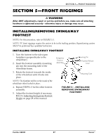 27
27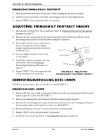 28
28 29
29 30
30 31
31 32
32 33
33 34
34 35
35 36
36

