Invacare PATRIOT Owners Manual - Page 43
Adjusting Quick-release Axles, Replacing Handrims
 |
View all Invacare PATRIOT manuals
Add to My Manuals
Save this manual to your list of manuals |
Page 43 highlights
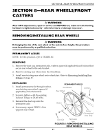
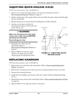
SECTION 8-REAR WHEELS/FRONT CASTERS ADJUSTING QUICK-RELEASE AXLES NOTE: For this procedure, refer to FIGURE 8.3. 1. Remove rear wheel and quick‐release axle from the wheelchair. Refer to Removing/Installing Rear Wheels on page 41. 2. Depress detent pin in the quick‐release axle and slide the quick‐release axle through the rear wheel hub. 3. Release detent pin to ensure that the locking pins are fully released. 4. Increase or decrease end play by adjusting the locknut on the end of the quick‐release axle. ƽ WARNING Make sure the detent pin of the quick release axle is fully released BEFORE operating the wheelchair. Wheelchair Frame Locknut Detent Pin Keep locking pins clean. 5. Reinstall rear wheel onto the wheelchair. Refer to Removing/Installing Rear Wheels on page 41. Locking Pin Axle Spacer (Conventional Arms Only) Quick-Release Axle Rear Wheel Hub 6. Repeat STEPS 4‐5 until the quick release axle detent pins are fully released past the wheelchair frame. FIGURE 8.3 - ADJUSTING QUICKRELEASE AXLES REPLACING HANDRIMS NOTE: for this procedure, refer to FIGURE 8.4. 1. Remove the rear wheel from the wheelchair. Refer to Removing/Installing Rear Wheels on page 41. 2. Remove the mounting screws that secure the existing handrim to the rear wheel. 3. Remove the existing handrim. 4. Install the new handrim and secure to the rear wheel with the existing mounting screws. 5. Reinstall the rear wheel to the wheelchair. Refer to Removing/Installing Rear Wheels on page 41. 6. Repeat STEPS 1‐5 for opposite wheel, if necessary. Part No 1088909 43 Patriot™
-
 1
1 -
2
-
3
-
4
-
5
-
6
-
7
-
8
-
9
-
10
-
11
-
12
-
13
-
14
-
15
-
16
-
17
-
18
-
19
-
20
-
21
-
22
-
23
-
24
-
25
-
26
-
27
-
28
-
29
-
30
-
31
-
32
-
33
-
34
-
35
-
36
-
37
-
 38
38 -
 39
39 -
 40
40 -
 41
41 -
 42
42 -
 43
43 -
 44
44 -
 45
45 -
 46
46 -
 47
47 -
 48
48 -
49
-
50
-
51
-
52
-
53
-
54
-
55
-
56
-
57
-
58
-
59
-
60
-
61
-
62
-
63
-
64
-
65
-
66
-
67
-
68
-
69
-
70
-
71
-
72
-
73
-
74
-
75
-
76
-
77
-
78
-
79
-
80
-
81
-
82
-
83
-
84
-
85
-
86
-
87
-
88
-
89
-
90
-
91
-
92
-
93
-
94
-
95
-
96
-
97
-
98
-
99
-
100
-
101
-
102
-
103
-
104
-
105
-
106
-
107
-
108
 |
 |
