Invacare PATRIOT Owners Manual
Invacare PATRIOT Manual
 |
View all Invacare PATRIOT manuals
Add to My Manuals
Save this manual to your list of manuals |
Invacare PATRIOT manual content summary:
- Invacare PATRIOT | Owners Manual - Page 1
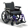
Owner's Operator and Maintenance Manual - English Manuel de L'utilisateur et D'entretien - French Canadian Patriot™ DEALER: This manual MUST be given to the user of the wheelchair. USER: BEFORE using this wheelchair, read this manual Invacare products, parts, and services, please visit www.invacare. - Invacare PATRIOT | Owners Manual - Page 2
ƽ WARNING DO NOT USE THIS PRODUCT OR ANY AVAILABLE OPTIONAL EQUIPMENT WITHOUT FIRST COMPLETELY READING AND UNDERSTANDING THESE INSTRUCTIONS AND ANY ADDITIONAL INSTRUCTIONAL MATERIAL SUCH AS OWNER'S MANUALS, SERVICE MANUALS OR INSTRUCTION SHEETS SUPPLIED WITH THIS PRODUCT OR OPTIONAL EQUIPMENT. IF - Invacare PATRIOT | Owners Manual - Page 3
SECTION 1-GENERAL GUIDELINES 9 Stability ...9 Anti-Tippers ...9 Repair and Service Information...10 Operating Information...10 Tire Pressure...11 Weight Training...12 Weight Limitation ...12 SECTION 2-SAFETY/HANDLING OF WHEELCHAIRS 13 Stability and Balance...13 Coping with Everyday Obstacles ...14 - Invacare PATRIOT | Owners Manual - Page 4
...25 Suggested Maintenance Procedures 25 Transporting the Invacare Patriot...26 SECTION 5-FRONT RIGGINGS 27 Installing/Removing Swingaway Footrest 27 Installing Swingaway Footrest ...27 Removing Swingaway Footrest ...28 Adjusting Swingaway Footrest Height 28 Removing/Installing Heel Loops ...28 - Invacare PATRIOT | Owners Manual - Page 5
ONLINE at warranty.invacare.com Please have your model number and purchase date available to complete your registration. Any registration information you submit will only be used by Invacare Corporation and protected as required by applicable laws and regulations. Part No 1088909 5 Patriot™ - Invacare PATRIOT | Owners Manual - Page 6
WHEELCHAIR USER As a manufacturer of wheelchairs, Invacare endeavors to supply a wide variety of wheelchairs to meet many needs of the end user. However, final selection of the type of wheelchair to be used by an individual rests in the event of a fall from a wheelchair. Patriot™ 6 Part No 1088909 - Invacare PATRIOT | Owners Manual - Page 7
tires). INSTRUCTIONS FOR WHEEL LOCK ADJUSTMENTS 1. Loosen wheel lock mounting fastener, which runs through mounting bracket and frame. 2. Slide clamp toward rear wheel until wheel lock shoe 4. Inspect for correct locking action BEFORE actual use. 00078X021-0394 Part No 1088909 7 Patriot™ - Invacare PATRIOT | Owners Manual - Page 8
- 29 lbs 250 lbs Patriot - 39.5lbs* *NOTE: 16x16 inch Seat Frame with packaging. NOTE: Invacare recommends that rear seat‐to‐floor heights be at least 3/8‐inch shorter than front seat‐to‐floor height. The seat‐to‐floor heights are based on urethane tires. If wheelchair is equipped with pneumatic - Invacare PATRIOT | Owners Manual - Page 9
safe operation and use of this product. wheelchair. Any change to one or any combination of the nine may cause the wheelchair depending on rear wheel size, rear wheel position, front caster manual for correct usage and adjustment. If these requirements cannot be achieved, DO NOT use the wheelchair - Invacare PATRIOT | Owners Manual - Page 10
‐tippers), Invacare strongly recommends ordering the anti‐tippers as a safeguard for the wheelchair user. wheelchair without assistance. DO NOT use an escalator to move a wheelchair between floors. Serious bodily injury may occur. DO NOT attempt to stop a moving wheelchair with the wheel locks. Wheel - Invacare PATRIOT | Owners Manual - Page 11
to the frame tubing. ALWAYS keep hands and fingers clear of moving parts to avoid injury. NEVER leave an unoccupied wheelchair on an incline. DO NOT use the footplates as a platform. When getting in or out of the wheelchair, make sure that the footplates are in the upward position or swing footrests - Invacare PATRIOT | Owners Manual - Page 12
kind of weight training. If occupant uses said wheelchair as a weight training apparatus, Invacare shall not be liable for bodily injury or physical disability and the warranty will be void. WEIGHT LIMITATION The Patriot wheelchair has a weight limitation of 250 lbs (114 kg). Patriot™ 12 Part No - Invacare PATRIOT | Owners Manual - Page 13
only as a "basic" guide. The techniques that are discussed on the following pages have been used successfully by many. Individual wheelchair users often develop skills to deal with daily living activities that may differ from those described in this manual. Invacare recognizes and encourages each - Invacare PATRIOT | Owners Manual - Page 14
have an effect on the center of gravity. Invacare recommends using seat positioning straps for additional safety while involved in activities that shift your weight. DO NOT lean forward out of the wheelchair any further than the length of the armrests. Make sure the casters are pointing in the - Invacare PATRIOT | Owners Manual - Page 15
on the removable (non‐ detachable) part of the wheelchair frame when lifting the wheelchair and stabilizing the wheelchair when the wheelchair is being lowered to the ground. The first assistant should stand on the sidewalk and turn the wheelchair so that the rear wheels are against the curb. The - Invacare PATRIOT | Owners Manual - Page 16
is advised when it is necessary to move an occupied wheelchair up or down the stairs. Invacare recommends using two assistants and making thorough preparations. Make sure to use only secure, non-detachable parts for hand-held supports. ALWAYS wear your seat positioning strap. Inasmuch as the seat - Invacare PATRIOT | Owners Manual - Page 17
mobility and upper body strength. 1. Position the wheelchair as close as possible along side the seat to which you are transferring, with the front casters parallel to it. 2. Engage wheel locks. 3. Remove or flip back armrests. 4. Shift body weight into seat with transfer. MAXIMUM GAP DISTANCE - Invacare PATRIOT | Owners Manual - Page 18
use of the wheelchair. CENTER OF GRAVITY UNOCCUPIED OCCUPIED FIGURE 2.4 - PERCENTAGE OF WEIGHT extended as far forward as possible and engage wheel locks. FIGURE 2.5 - REACHING, LEANING AND parts to avoid injury. NOTE: For this procedure, refer to FIGURE 2.6 Patriot™ 18 Part No 1088909 - Invacare PATRIOT | Owners Manual - Page 19
where the seat upholstery is attached until the wheelchair is fully open. 4. Engage both wheel locks, open the footrest/legrest for clearance and transfer into the wheelchair. Refer to Transferring To and From Other Seats on page 17. FIGURE 2.7 - UNFOLDING SLING SEAT Part No 1088909 19 Patriot™ - Invacare PATRIOT | Owners Manual - Page 20
the seat to the hinged side. 3. Swing footrest/legrest in locked position to the front of the wheelchair. 4. Pivot footplates upward to vertical position. wheelchair to one side and close by the push handles. FIGURE 2.9 - UNFOLDING/FOLDING SOLID SEAT MODEL WHEELCHAIRS Patriot™ 20 Part No 1088909 - Invacare PATRIOT | Owners Manual - Page 21
3-SAFETY INSPECTION/ TROUBLESHOOTING NOTE: Twice a year, take your wheelchair to a qualified dealer for a thorough inspection and servicing. Regular cleaning will reveal loose or worn parts and enhance the smooth operation of your wheelchair. To operate properly and safely, your wheelchair must be - Invacare PATRIOT | Owners Manual - Page 22
from dirt, lint, etc. ❑ Ensure roller bearings are free from dirt, lint, etc. ❑ Adjust wheel locks as tires wear. ❑ Clean and wax all parts. ❑ Clean upholstery and armrests. INSPECT/ADJUST WEEKLY ❑ Wheelchair rolls straight (no excessive drag or pull to one side). ❑ Quick‐release axles lock properly - Invacare PATRIOT | Owners Manual - Page 23
axles are free from dirt, lint, etc. ❑ Ensure roller bearings are free from dirt, lint, etc. ❑ Adjust wheel locks as tires wear. ❑ Clean and wax all parts. ❑ Check that all labels are present and legible. Replace if necessary. ❑ Ensure that casters are free of debris. Part No 1088909 23 Patriot™ - Invacare PATRIOT | Owners Manual - Page 24
RATTLES LOOSENESS IN CHAIR CHAIR 3 WHEELS SOLUTIONS X X X X If pneumatic tires, check for correct and equal pressure. X X X X Check for loose stem nuts/bolts. X X X Check caster angle adjustment. X X Check that casters contact ground at the same time. Patriot™ 24 Part No 1088909 - Invacare PATRIOT | Owners Manual - Page 25
DO NOT overtighten hardware attaching to the frame. This could cause damage to the frame tubing. SUGGESTED MAINTENANCE PROCEDURES 1. Before using your Patriot, make sure all nuts and bolts are tight. Check all parts for damage or wear and replace. Check all parts for proper adjustment. 2. Keep quick - Invacare PATRIOT | Owners Manual - Page 26
/TRANSPORTING TRANSPORTING THE INVACARE PATRIOT 1. Remove the seating system. Refer to the seating system Owner's Manual for installation and removal of the seating system. 2. Remove the footrests. Refer to Installing/Removing Swingaway Footrest on page 27. 3. Remove the rear wheels. Refer to - Invacare PATRIOT | Owners Manual - Page 27
footrest assembly. 5. Adjust the footrest height, if necessary. Refer to Adjusting Swingaway Footrest Height on page 28 of the manual. Swingaway Footrest Assembly Mounting Pin Footrest Release Lever Mounting Tube FIGURE 5.1 - INSTALLING/ REMOVING SWINGAWAY FOOTREST Part No 1088909 27 Patriot - Invacare PATRIOT | Owners Manual - Page 28
spacer. 5. Install the footrest assembly onto the wheelchair. Refer to Installing/ Removing Swingaway Footrest on page 27. Hex Screw Coved Spacer Footrest Footrest Upper Support Mounting Tube 6. Repeat the new heel loop. Refer to Installing Heel Loops on page 29. Patriot™ 28 Part No 1088909 - Invacare PATRIOT | Owners Manual - Page 29
on the wheelchair frame. 3. Rotate legrest/calfpad assembly toward the inside of the wheelchair until it locks in place. NOTE: The calfpad of the legrest will be on the inside of the wheelchair when locked in place. 4. Repeat STEPS 1‐3 for opposite legrest assembly. Part No 1088909 29 Patriot™ - Invacare PATRIOT | Owners Manual - Page 30
footrest outward. 2. Lift legrest assembly out of the legrest mounting tube. Mounting Tube Mounting Pin Legrest Release Handle Legrest Support wheelchair. Release Lever Calf Pad Rotated For Height Adjustment Calf Pad FIGURE 5.5 - ADJUSTING ELEVATING LEGREST/CALFPAD ASSEMBLY Patriot™ 30 Part - Invacare PATRIOT | Owners Manual - Page 31
wheelchair can operate the footplates easily. NOTE: If the footplateʹs motion is too tight, loosen the socket screw and locknut approximately ¼ turn. NOTE: If the footplateʹs motion is too loose, tighten socket screw and locknut approximately ¼ turn. Locknut Footplate Hinge Footrest Support Tube - Invacare PATRIOT | Owners Manual - Page 32
eversion is obtained. 90° Footrest Support Flat Screws DETAIL "A" - SIDE VIEW OF FOOTPLATE AND FOOTREST SUPPORT Footrest Support Footplate Footplate Half Clamp Footplate Hinge Adjustment Screw Locknuts FIGURE 5.7 - ADJUSTING ADJUSTABLE ANGLE FLIP-UP FOOTPLATES Patriot™ 32 Part No 1088909 - Invacare PATRIOT | Owners Manual - Page 33
, repair or service and BEFORE use, make sure all attaching hardware is tightened securely - otherwise injury or damage may occur. ADJUSTING/USING ARMREST ƽ WARNING Make sure the height adjustment lever is in the locked position before using the wheelchair. ADJUSTING ARMREST HEIGHT NOTE: For - Invacare PATRIOT | Owners Manual - Page 34
manual. INSTALLING FLIP BACK ARMREST 1. If necessary, unlock new/existing armrest assembly by flipping the arm assembly release levers located on the side rail to the UP (horizontal) position as shown in Detail ʺAʺ. 2. Install new/existing armrest assembly into the arm sockets. Patriot™ 34 Part - Invacare PATRIOT | Owners Manual - Page 35
ʺAʺ is a top view of the armrest release levers. Right side and left side are determined by sitting in the wheelchair. Armrest Release Lever Arm Socket Height Adjustment Lever Armrest Release Lever Arm Socket FIGURE 6.3 - REMOVING/INSTALLING FLIP BACK ARMREST Part No 1088909 35 Patriot™ - Invacare PATRIOT | Owners Manual - Page 36
or service and BEFORE use, make sure all attaching hardware is tightened securely - otherwise injury or damage may occur. REMOVING/INSTALLING SEAT UPHOLSTERY NOTE: For this procedure, refer to FIGURE 7.1. REMOVING SEAT UPHOLSTERY 1. If necessary, remove the seat cushion from the wheelchair - Invacare PATRIOT | Owners Manual - Page 37
frame with the tie wraps. Back Mounting Cane Screw Back Cane Washer Mounting Screw Locknut Back Upholstery Wheelchair Frame FIGURE 7.2 - REMOVING/ INSTALLING BACK UPHOLSTERY 7. Rotate the flip back arms down. Refer to Adjusting/Using Armrest on page 33. Part No 1088909 37 Patriot - Invacare PATRIOT | Owners Manual - Page 38
. The adjustable back should be checked whenever entering the wheelchair to ensure that the fastening straps are securely fastened. Frame Adjustable Back Upholstery Mounting Screws Adjustable Back Upholstery Washers FIGURE 7.3 - ADJUSTING ADJUSTABLE TENSION BACK UPHOLSTERY Patriot™ 38 Part - Invacare PATRIOT | Owners Manual - Page 39
the seat positioning strap, proceed to STEP 6. B. Remove the existing seat positioning strap from the wheelchair. 6. Engage the two halves of the new seat positioning strap. 7. Position one end of the same way. FIGURE 7.4 - INSTALLING/REMOVING SEAT POSITIONING STRAP Part No 1088909 39 Patriot™ - Invacare PATRIOT | Owners Manual - Page 40
NOTE: Only hook and loop style chest positioning strap shown. Auto style chest positioning strap attaches the same way. FIGURE 7.5 - INSTALLING/REMOVING CHEST POSITIONING STRAP Patriot™ 40 Part No 1088909 - Invacare PATRIOT | Owners Manual - Page 41
CASTERS ƽ WARNING After ANY adjustments, repair or service and BEFORE use, make sure all attaching hardware is tightened securely - otherwise injury or damage may occur. REMOVING/INSTALLING REAR WHEELS ƽ WARNING If changing the size of the rear wheel or the seat-to-floor height, this procedure - Invacare PATRIOT | Owners Manual - Page 42
not protruding past the inside of the axle bushing or there is too much movement of the rear wheel assembly in a back and forth position. QUICK-RELEASE AXLES Rear Wheel Wheelchair Frame Patriot™ Quick-Release Axle Axle Bracket FIGURE 8.2 REMOVING/INSTALLING REAR WHEELS 42 Part No 1088909 - Invacare PATRIOT | Owners Manual - Page 43
detent pins are fully released past the wheelchair frame. FIGURE 8.3 - ADJUSTING QUICKRELEASE AXLES REPLACING HANDRIMS NOTE: for this procedure, refer to FIGURE 8.4. 1. Remove the rear wheel from the wheelchair. Refer to Removing/Installing Rear Wheels on page 41. 2. Remove the mounting screws - Invacare PATRIOT | Owners Manual - Page 44
REAR WHEELS/FRONT CASTERS Rear Wheel Mounting Screws Handrim FIGURE 8.4 - REPLACING HANDRIMS REPLACING/REPAIRING REAR WHEEL TIRE/TUBE ƽ WARNING Replacement of rear wheel tire or tube MUST be performed by a qualified technician. REPLACING/REPAIRING FRONT CASTER TIRE/TUBE ƽ WARNING Replacement of - Invacare PATRIOT | Owners Manual - Page 45
STEPS C‐D until the wheels swing once to one‐side, then immediately rest in a straight downward position. 4. Test wheelchair for maneuverability. 5. Snap dust cover into the caster headtube. Dust cover Locknut Caster Headtube Fork Caster FIGURE 8.5 - ADJUSTING FORKS Part No 1088909 45 Patriot™ - Invacare PATRIOT | Owners Manual - Page 46
this manual for correct usage and adjustment. If these requirements cannot be achieved, DO NOT use the wheelchair. wheels and the ground/ floor. NOTE: A 1‐1/2 to 2‐inch clearance between the bottom of the anti‐tipper wheels and the ground/ floor MUST be maintained at all times. Patriot™ 46 Part - Invacare PATRIOT | Owners Manual - Page 47
that the release buttons are fully engaged in adjustment holes. Anti-Tipper Wheel FIGURE 9.1 - INSTALLING ANTITIPPERS Wheelchair Frame Release Buttons 1½ to 2 inch Clearance FIGURE 9.2 - - INSTALLING on a flat surface. Anti-tipper Height Anti-tipper Length Part No 1088909 47 Patriot™ - Invacare PATRIOT | Owners Manual - Page 48
inches 12¾, 2¼ inches 10, 1¾ inches ON CHAIR N/A N/A N/A OFF CHAIR KIT NUMBER 1090114 1090115 1090116 *NOTE: SHE stands for Super Hemi wheelchairs that have a 15½ inch seat‐to‐floor height. USING/ADJUSTING WHEEL LOCKS (PUSH-TOLOCK/PULL-TO-LOCK) USING WHEEL LOCKS PUSH-TO-LOCK ƽ WARNING DO NOT - Invacare PATRIOT | Owners Manual - Page 49
Lock Shoe Spacers on page 49. 2. Loosen the bolt and locknut that secure the wheel lock assembly to the wheelchair frame. 3. Adjust the position of wheel lock until the measurement between the rear wheel and the wheel lock shoe or shoe spacer is between 5/32 and 5/16‐inches. 4. Securely tighten the - Invacare PATRIOT | Owners Manual - Page 50
‐to‐Lock ‐ To engage, push the wheel lock handle FORWARD. B. Pull‐to‐Lock ‐ To engage, pull the wheel lock handle BACKWARD. 3. Disengage the wheel locks by reversing STEP 2. Wheel Lock PULL-TO-LOCK PUSH-TO-LOCK Wheel Lock FIGURE 9.6 - USING HIGH MOUNT WHEEL LOCKS Patriot™ 50 Part No 1088909 - Invacare PATRIOT | Owners Manual - Page 51
wheelchair frame. Socket Screws Wheelchair Frame 3. Measure the distance between the wheel lock shoe and the rear wheel. 4. Slide the wheel lock along the wheelchair until the measurement is between 5/32 and 5/16‐inches. Wheel Lock Rear Wheel 5. Tighten the wheel lock to the wheelchair frame - Invacare PATRIOT | Owners Manual - Page 52
Washer (STEP 6) Spacer (STEP 3) Button Screw (STEPS 2 and 4) Wheel Lock Extension Handle (STEP 5) Existing Handle (STEP 9) Wheel Lock Assembly (STEP 2) Locknut (STEPS 2 and 4) Washer (STEPS 2 and 4) FIGURE 9.8 - HIGH MOUNT WHEEL LOCK EXTENSION HANDLE INSTALLATION Patriot™ 52 Part No 1088909 - Invacare PATRIOT | Owners Manual - Page 53
include any labor or shipping charges incurred in replacement part installation or repair of any such product. Invacare's sole obligation and your exclusive remedy under this warranty shall be limited to such repair and/or replacement. For warranty service, please contact the dealer from whom you - Invacare PATRIOT | Owners Manual - Page 54
les accessoires Invacare. Les accessoires conçus par d'autres fabricants n'ont pas été testés par Invacare. Il n'est donc pas recommandé de les utiliser avec des produits Invacare. REMARQUE : Des versions à jour de ce manuel se trouvent sur le site www.invacare.com. Patriot™ 54 Part No 1088909 - Invacare PATRIOT | Owners Manual - Page 55
é...74 Inspecter/Régler (Initial) ...74 Inspecter/Régler Une Fois Par Semaine 75 Inspecter/Régler Une Fois Par Mois 76 Inspecter/Régler Périodiquement...76 Dépannage ...77 Part No 1088909 55 Patriot™ - Invacare PATRIOT | Owners Manual - Page 56
curité Pour L'entretien 78 Procédures D'entretien Suggérées 78 Transporter Le Fauteuil Patriot ...79 SECTION 5-APPUIE-PIEDS\JAMBES 80 Installer/Enlever Les Appuie-pieds Pivotants 80 Installer /Enlever les Ceintures...92 Installer/Enlever la Ceinture Thoracique 93 Patriot™ 56 Part No 1088909 - Invacare PATRIOT | Owners Manual - Page 57
Les Dispositifs De Blocage Surélevés Des Roues 104 Installer Les Poignées De Rallonge Des Dispositifs De Blocage Des Roues 105 GARANTIE LIMITÉE 107 Part No 1088909 57 Patriot™ - Invacare PATRIOT | Owners Manual - Page 58
conseils pour l'entretien et des nouvelles de l'industrie. Enregistrez-vous EN LIGNE sur warranty.invacare.com Veuillez avoir à portée de main votre numéro de modèle ainsi que utilisées que par Invacare Corporation et protégées par les lois et règlements en vigueur. Patriot™ 58 Part No 1088909 - Invacare PATRIOT | Owners Manual - Page 59
des soins de santé en mesure de faire ce choix. SUPPORT D'ARRIMAGE ET CEINTURES POUR FAUTEUILS ROULANTS Invacare recommande de NE PAS transporter les utilisateurs de fauteuils roulants à blessures graves peuvent survenir si l'utilisateur tombe du fauteuil. Part No 1088909 59 Patriot™ - Invacare PATRIOT | Owners Manual - Page 60
besoins, suivre les instructions suivantes. ! ATTENTION INSTRUCTIONS POUR RÉGLER LES FREINS DE BLOCAGE 1. Desserrer l'attache du frein de blocage qui passe dans le support frein de blocage pour fixer le support de montage à l'endroit voulu et WARNING Refer to the Owner's Manual for proper anti-tipper - Invacare PATRIOT | Owners Manual - Page 61
POIDS: Patriot - 29 lbs LIMITE DE POIDS: 250 lbs POIDS À LA LIVRAISON (APPROXIMATE): Patriot - 39.5lbs* REMARQUE: Châssis de siège de 16x16 po. avec emballage. REMARQUE: Invacare recommande que à + ou ¼ po à cause de l'usure et de la pression des pneus. Part No 1088909 61 Patriot™ - Invacare PATRIOT | Owners Manual - Page 62
diamètre\position des roues avant et l'angle entre le sol et le siège. Ce réglages DOIVENT être exécutés par un technicien qualifié. Patriot™ 62 Part No 1088909 - Invacare PATRIOT | Owners Manual - Page 63
sur les fauteuils 0° ou 3° (vous pouvez les commander avec ou sans les antibascules), Invacare recommande fortement de commander les antibascules pour plus de sécurité pour lʹutilisateur. Angle siège roulant pour changer dʹétage. De graves blessures peuvent survenir. Part No 1088909 63 Patriot™ - Invacare PATRIOT | Owners Manual - Page 64
sur ce fauteuil (vous pouvez le commander avec ou sans la ceinture de siège\thoracique), Invacare recommande fortement de commander la ceinture de siège et\ou thoracique comme mesure de sécurité en tirant sur les gaines si elles sont non sécuritaires ou endommagées. Patriot™ 64 Part No 1088909 - Invacare PATRIOT | Owners Manual - Page 65
cerceaux de conduite), Invacare recommande fortement de pneus. Si vous ne suivez pas ces instructions, les pneus pourraient éclater et causer des Invacare recommande de ne pas utiliser ces fauteuils comme appareil de musculation. Les fauteuils Invacare appareil de musculation, Invacare ne sera pas tenu - Invacare PATRIOT | Owners Manual - Page 66
les obstacles architecturaux courants. Utiliser cette information comme guide de base seulement. Les techniques présentées dans des rampes ou des pentes de plus de 9° d'inclinaison. Invacare recommande fortement de descendre les rampes ou les pentes lentement pour . Patriot™ 66 Part No 1088909 - Invacare PATRIOT | Owners Manual - Page 67
qui impliquent des mouvements ont un effet sur le centre de gravité. Pour plus de sécurité, Invacare recommande dʹutiliser les ceintures pendant les activités qui vous obligent à déplacer votre poids. NE traverser les rebords de trottoirs, les petites marches, etc. Part No 1088909 67 Patriot™ - Invacare PATRIOT | Owners Manual - Page 68
retomber sur le sol. Ceci pourrait causer des blessures à l'utilisateur. Push the wheelchair forward until the rear wheels roll up and over the curb. FIGURE 2.1 MÉTHODE 1- FAUTEUIL AVEC TUBES SURE loigné du rebord. FIGURE 2.2 MÉTHODE 2 - FAUTEUIL SANS TUBE D'APPUI Patriot™ 68 Part No 1088909 - Invacare PATRIOT | Owners Manual - Page 69
optionnelles sur ce fauteuil vous pouvez commander le fauteuil avec ou sans les ceintures, Invacare recommande fortement de commander la ceinture et la ceinture thoracique pour plus de sécurit PAS utiliser les escaliers roulants. Des blessures graves peuvent survenir. Part No 1088909 69 Patriot™ - Invacare PATRIOT | Owners Manual - Page 70
neuf combinaisons peut diminuer la stabilité. Ces réglages doivent être exécutés par un technicien qualifié. REMARQUE: Pour cette procédure, se référer à la FIGURE 2.4. Patriot™ 70 Part No 1088909 - Invacare PATRIOT | Owners Manual - Page 71
soient dirigées le plus possible vers lʹavant, et enclencher le dispositif de blocage des roues. FIGURE 2.5 - S'ÉTIRER, SE PENCHER ET SE PLIER VERS L'AVANT Part No 1088909 71 Patriot™ - Invacare PATRIOT | Owners Manual - Page 72
ou les ramasser sur le plancher en vous penchant entre vos genoux. Keep hands and fingers clear of moving parts to avoid injury. REMARQUE: Pour cette procédure, se référer à la FIGURE 2.6 Placer le fauteuil À Un Autre de la page 70. FIGURE 2.7 - DÉPLIER LE FAUTEUIL Patriot™ 72 Part No 1088909 - Invacare PATRIOT | Owners Manual - Page 73
sur un côté et fermer avec les poignées pousettes. FIGURE 2.9 - OUVRIR LE MODÈLE À SIÈGE RIGIDE ET FERMER LE MODÈLE À SIÈGE RIGIDE Part No 1088909 73 Patriot™ - Invacare PATRIOT | Owners Manual - Page 74
s'il y a des rayons brisés . ❑ 'L'ensemble roue/fourche a la bonne tension lorsque la roue avant est tournée (roulement libre). La roue avant devrait s'arrêter graduellement. Patriot™ 74 Part No 1088909 - Invacare PATRIOT | Owners Manual - Page 75
y déceler la présence de points plats ou d'usure. ❑ Vérifier la pression des pneus pneumatiques (la pression recommandée est indiquée sur la paroi du pneu). Part No 1088909 75 Patriot™ - Invacare PATRIOT | Owners Manual - Page 76
roue vibre ou arrêt d'un coup. ❑ S'assurer que les roulements des roues sont propres, sans poussières, etc. ❑ Les freins de blocage sont faciles à enclencher. Patriot™ 76 Part No 1088909 - Invacare PATRIOT | Owners Manual - Page 77
. X X X S'assurer que les roues avant touchent le sol en même temps. X X Si les pneus sont pneumatiques, vérifier si la pression est adéquate et égale. Part No 1088909 77 Patriot™ - Invacare PATRIOT | Owners Manual - Page 78
pas adéquate (p.s.i.). NE PAS trop gonfler les pneus. Si vous ne respectez pas ces instructions, les pneus pourraient éclater et causer des blessures corporelles. 3. La pression recommandée pour propres et exempt dʹhumidité. Utiliser un lubrifiant Téflon si nécessaire. Patriot™ 78 Part No 1088909 - Invacare PATRIOT | Owners Manual - Page 79
TRANSPORT 8. Vérifier si la garniture est lâche, déchirée ou abîmée. TRANSPORTER LE FAUTEUIL PATRIOT 1. Enlever le système de siège. Se référer au manuel de lʹutilisateur du 87. 5. Enlever les antibascules. Se référer à Installer/Régler Les Antibascules de la page 99. Part No 1088909 79 Patriot™ - Invacare PATRIOT | Owners Manual - Page 80
PIVOTANTS ENLEVER LES APPUIE-PIEDS PIVOTANTS 1. Pousser le levier de dégagement de l'appuie‐pied vers l'intérieur tout en tournant l'appuie‐pied vers l'extérieur. Patriot™ 80 Part No 1088909 - Invacare PATRIOT | Owners Manual - Page 81
tube de montage à la hauteur voulue. 3. Remonter la vis hexagonale et l'intercalaire bombé dans le support supérieur et le tube de montage tel qu'illustré à la FIGURE 5.2. 4. Bien serrer la du tube de montage. 5. Répéter les ÉTAPES 1‐4 pour l'autre côté, si nécessaire. Part No 1088909 81 Patriot™ - Invacare PATRIOT | Owners Manual - Page 82
lʹécrou de blocage jusquʹà ce que lʹintercalaire soit fixe. 3. Fixer le tube de montage et lʹappuie‐ pied au support supérieur de lʹappuie‐ pied, tel quʹillustré à la FIGURE 5.2. 4. Répéter les ÉTAPES 1‐3 pour l' . À la hauteur voulue, bien serrer le boulon et l'écrou. Patriot™ 82 Part No 1088909 - Invacare PATRIOT | Owners Manual - Page 83
Soulever les jambes à la hauteur voulue en soulevant les palettes. 2. Pour replacer l'appuie‐jambe à la position normale, supporter la jambe d'une main et pousser le levier de dégagement avec l'autre main ÉES REMARQUE: Pour cette procédure, se référer à la FIGURE 5.6. Part No 1088909 83 Patriot™ - Invacare PATRIOT | Owners Manual - Page 84
Serrer la vis à tête creuse et l'écrou de blocage qui fixent la charnière de la palette au support de l'appuie‐pied jusqu'à ce que la charnière de la palette demeure en haut. 5. Vérifierle mouvement 3. Resserrer les deux vis à tête plate et les écrous de blocage. Patriot™ 84 Part No 1088909 - Invacare PATRIOT | Owners Manual - Page 85
de l'appuie-pied90° Vis à tête plate SCHÉMA "A" - VUE LATÉRALE DE LA PALETTE ET DU SUPPORT DE L'APPUIE-PIE Support de l'appuie-pied Palette Palette Demi pince Charnière de la palette Vis de réglage Écrous de blocage FIGURE 5.7 - RÉGLER LES PALETTES ARTICULÉES Part No 1088909 85 Patriot™ - Invacare PATRIOT | Owners Manual - Page 86
ÉMA "A" Appuie-bras Levier de réglage de la hauteur Bloqué - Vers le bas (Position Verticale) Débloqué - Vers le haut (Position Horizontale) FIGURE 6.1 - RÉGLER L'APPUIE-BRAS Patriot™ 86 Part No 1088909 - Invacare PATRIOT | Owners Manual - Page 87
dégagement de l'appuie-bras Arrière Encastrement de l'appuiebras FIGURE 6.2 - UTILISER ENLEVER/INSTALLER L'APPUIE-BRAS RABATTABLE REMARQUE: Pour cette procédure, se référer à la FIGURE 6.3. Part No 1088909 87 Patriot™ - Invacare PATRIOT | Owners Manual - Page 88
de l'appuie-bras Levier de réglage de l'appuie-bras Levier de dégagement de l'appuie-bras Encastrement de l'appuie-bras FIGURE 6.3 - ENLEVER/INSTALLER L'APPUIE-BRAS RABATTABLE Patriot™ 88 Part No 1088909 - Invacare PATRIOT | Owners Manual - Page 89
les rondelles qui fixent la garniture de siège nouvelle ou existante aux croisillons. 3. Si nécessaire, réinstaller le coussin du siège sur le fauteuil. Part No 1088909 89 Patriot™ - Invacare PATRIOT | Owners Manual - Page 90
fauteuil avec les serre‐ fils. 7. Tourner les appuie‐bras rabattables vers le bas. Se référer à Installer La Garniture Du Siège de la page 89. Patriot™ 90 Part No 1088909 - Invacare PATRIOT | Owners Manual - Page 91
dossier réglable Boucle d'ancrage Courroie de réglage Châssis Vis de montage Rondelles Garniture de dossier réglable FIGURE 7.3 - RÉGLER LA GARNITURE DE DOSSIER À TENSION RÉGLABLE Part No 1088909 91 Patriot™ - Invacare PATRIOT | Owners Manual - Page 92
: Seules les ceintures à boucle ou à crochet sont illustrées. Les ceintures de type automobile sʹinstallent de la même façon. FIGURE 7.4 - INSTALLER/ENLEVER LES CEINTURES Patriot™ 92 Part No 1088909 - Invacare PATRIOT | Owners Manual - Page 93
les ceintures à boucle ou à crochet sont illustrées. Les ceintures de type automobile sʹinstallent de la même façon. FIGURE 7.5 - INSTALLER/ENLEVER LA CEINTURE THORACIQUE Part No 1088909 93 Patriot™ - Invacare PATRIOT | Owners Manual - Page 94
, lʹintercalaire (sʹil y a lieu) et lʹécrou de blocage qui fixent la roue arrière au support de lʹessieu. 2. Enlever la roue arrière existante du fauteuil. ESSIEUX FIXES 3. Installer la Roue GAGEMENT RAPIDE REMARQUE: Pour cette procédure, se référer à la FIGURE 8.2. Patriot™ 94 Part No 1088909 - Invacare PATRIOT | Owners Manual - Page 95
assurer un blocage adéquat. Garder les tiges de blocage propres. Invacare recommande d'insérer les essieux à dégagement rapide en placant arrière nouvelle ou existante et lʹessieu à dégagement rapide dans le support de lʹessieu sur le châssis du fauteuil. 3. Si les tiges Part No 1088909 95 Patriot™ - Invacare PATRIOT | Owners Manual - Page 96
ère. 3. Enlever le cerceau de conduite existant. 4. Installer le nouveau cerceau de conduite et fixer à la roue arrière avec les même vis de montage. Patriot™ 96 Part No 1088909 - Invacare PATRIOT | Owners Manual - Page 97
és périodiquement pour s'assurer qu'ils ne sont pas usés ou fendus, et doivent être remplacés, si nécessaire. RÉGLER LES ROUES AVANT/DISTANCE SIÈGE/SOL Part No 1088909 97 Patriot™ - Invacare PATRIOT | Owners Manual - Page 98
TAPES C‐D jusquʹà ce que les roues avant balancent une fois et sʹimmobilisent immédiatement en position droite. 4. Vérifier la manoeuvrabilité du fauteuil. 5. Replacer le capuchon contre la poussière sur lʹencastrements de la roue avant. Capuchon contre la poussière Écrou de blocage Encastrement de - Invacare PATRIOT | Owners Manual - Page 99
optionnels sur les fauteuils 0° ou 3° (vous pouvez les commander avec ou sans les antibascules), Invacare recommande fortement de commander les antibascu-les pour plus de sécurité pour l'utilisateur. Angle siège la base des roues des antibascules et le sol/plancher. Part No 1088909 99 Patriot™ - Invacare PATRIOT | Owners Manual - Page 100
. Se référer à régler les antibascules dans cette procédure du manuel. PATRIOT Boutons de dégagement Roue de l'antibascule Antibascule Tube du châssis arrière FIGURE antibascules sont sur une surface plane. Patriot™ Hauteur de l'antibascule Longueur de l'antibascule 100 Part No 1088909 - Invacare PATRIOT | Owners Manual - Page 101
3½-po. 12¾, 2-7/8-po. INSTALLÉ SUR FAUTEUIL P1580 P1580A P1580SHE LIBRE (NO. ENS.) 1090113 1050644 1050641 PATRIOT AVEC ANGLE SIÈGE/SOL DE 6° DISTANCE SIÈGE/SOL 17½,18½,19½-po. 16½,17½-po. 15 senclencher les dispositifs de blocage des roues en inversant lʹÉTAPE 2. Part No 1088909 101 Patriot™ - Invacare PATRIOT | Owners Manual - Page 102
lʹécrou de blocage qui fixent le dispositif de blocage au châssis du fauteuil et installer le dispositif dans un des deux orifices de montage. Patriot™ 102 Part No 1088909 - Invacare PATRIOT | Owners Manual - Page 103
dispositif de blocage Vis d'arrêt Intercalaire du sabot du dispositif de blocage Côté biseauté FIGURE 9.5 - INSTALLER LES INTERCALAIRES DES SABOTS DES DISPOSITIFS DE BLOCAGE DES ROUES Part No 1088909 103 Patriot™ - Invacare PATRIOT | Owners Manual - Page 104
arrière. 4. Glisser le dispositif de blocage des roues le long du fauteuil jusqu'à ce qu'il y ait une distance de 5/32 et 5/16‐po. Patriot™ 104 Part No 1088909 - Invacare PATRIOT | Owners Manual - Page 105
en fonction des besoins de l'utilisateur. 5. Pousser l'extrémité opposée du cordon élastique dans l'orifice fendu de la poignée du dispositif de blocage des roues. Part No 1088909 105 Patriot™ - Invacare PATRIOT | Owners Manual - Page 106
(ÉTAPE 2) Rondelle (ÉTAPES 2 ET 4) Poignée EXISTANTE (ÉTAPE 9) Écrou de blocage (ÉTAPES 2 ET 4) FIGURE 9.8 - INSTALLER LES POIGNÉES DE RALLONGE DES DISPOSITIFS DE BLOCAGE DES ROUES Patriot™ 106 Part No 1088909 - Invacare PATRIOT | Owners Manual - Page 107
produits endommagés dans des circonstances au-delà du contrôle d'INVACARE, et l'évaluation sera faite par INVACARE. La garantie ne s'applique pas aux problèmes découlant de l'usure normale ou de la négligence à respecter les instructions ci-incluses. La présente garantie est exclusive et remplace - Invacare PATRIOT | Owners Manual - Page 108
identified by the symbols ™ and ®. All trademarks are owned by or licensed to Invacare Corporation or its subsidiaries unless otherwise noted. 3-in-1 oil is a registered trademark of trademark of E.I. Du Pont De Nemours and Company. © 2009 Invacare Corporation Part No 1088909 Rev E - 2/09
-
 1
1 -
 2
2 -
 3
3 -
 4
4 -
 5
5 -
 6
6 -
 7
7 -
8
-
9
-
10
-
11
-
12
-
13
-
14
-
15
-
16
-
17
-
18
-
19
-
20
-
21
-
22
-
23
-
24
-
25
-
26
-
27
-
28
-
29
-
30
-
31
-
32
-
33
-
34
-
35
-
36
-
37
-
38
-
39
-
40
-
41
-
42
-
43
-
44
-
45
-
46
-
47
-
48
-
49
-
50
-
51
-
52
-
53
-
54
-
55
-
56
-
57
-
58
-
59
-
60
-
61
-
62
-
63
-
64
-
65
-
66
-
67
-
68
-
69
-
70
-
71
-
72
-
73
-
74
-
75
-
76
-
77
-
78
-
79
-
80
-
81
-
82
-
83
-
84
-
85
-
86
-
87
-
88
-
89
-
90
-
91
-
92
-
93
-
94
-
95
-
96
-
97
-
98
-
99
-
100
-
101
-
102
-
103
-
104
-
105
-
106
-
107
-
108
 |
 |
Owner’s Operator and Maintenance Manual - English
Manuel de L’utilisateur et D’entretien - French
Canadian
DEALER:
This manual MUST be given to
the user of the wheelchair.
USER:
BEFORE using this wheelchair, read
this manual and save for future reference.
FOURNISSEUR:
Ce manuel doit être
remis à l’utilisateur du fauteuil roulant.
UTILISATEUR:
Avant d’utiliser ce fauteuil
roulant, lire ce manuel et le conserver à titre
de référence.
For more information regarding
Invacare products,
parts, and services,
please visit www.invacare.com
Pour de plus amples renseignements sur les
produits,les pièces et le service
Invacare,consulter le: www.invacare.com
Patriot™