Invacare JASMINE Owners Manual - Page 10
Assembly
 |
View all Invacare JASMINE manuals
Add to My Manuals
Save this manual to your list of manuals |
Page 10 highlights
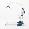
SECTION 2-ASSEMBLY SECTION 2-ASSEMBLY Assembling the Patient Lift Assembling the Mast Assembly to the Base NOTE: The mast assembly may be removed from the base for storage or transporting. The mast assembly MUST be properly secured to the base assembly before use. NOTE: For this procedure, refer to FIGURE 2.1. 1. Put the base on a level surface so all casters make contact with the floor. 2. Lock the rear casters. Refer to Detail "A". 3. Unscrew the top knob and remove it from the base. 4. Loosen the bottom knob, but leave it screwed into the base. 5. Put the tube of the mast assembly into the hole in the base. 6. While supporting the mast assembly, tighten the bottom plastic knob. 7. Screw the top plastic knob into the hole in the base. DETAIL "A" Push tab down to lock Push tab up to unlock Mast Assembly Base Caster Top Plastic Knob Bottom Plastic Knob FIGURE 2.1 Assembling the Mast Assembly to the Base Jasmine™ Patient Lift 10 Part No 1150704
-
 1
1 -
2
-
3
-
4
-
 5
5 -
 6
6 -
 7
7 -
 8
8 -
 9
9 -
 10
10 -
 11
11 -
 12
12 -
 13
13 -
 14
14 -
 15
15 -
16
-
17
-
18
-
19
-
20
-
21
-
22
-
23
-
24
-
25
-
26
-
27
-
28
-
29
-
30
-
31
-
32
-
33
-
34
-
35
-
36
-
37
-
38
-
39
-
40
-
41
-
42
-
43
-
44
-
45
-
46
-
47
-
48
-
49
-
50
-
51
-
52
-
53
-
54
-
55
-
56
-
57
-
58
-
59
-
60
-
61
-
62
-
63
-
64
-
65
-
66
-
67
-
68
 |
 |
