Dell Latitude 9510 Service Manual - Page 13
Disassembly and reassembly, SIM card tray, Removing the SIM card tray
 |
View all Dell Latitude 9510 manuals
Add to My Manuals
Save this manual to your list of manuals |
Page 13 highlights
Table 1. Latitude 9510 screw list (continued) Component Screw type M1.6x3.5 Power button M1.5x2.5 M2.5x5 Quantity 1 3 3 Fingerprint bracket M1.5x2.5 3 System board M1.6x3.5 9 M2.5x5 1 M1.6x4.5 1 Keyboard M1.6x2 4 M1.6x1.5 36 Disassembly and reassembly SIM card tray Removing the SIM card tray Prerequisites Follow the procedure in before working inside your computer. About this task The following image provides a visual representation of the SIM card tray removal procedure. Image Removing and Installing Components 13
-
 1
1 -
2
-
3
-
4
-
5
-
6
-
7
-
 8
8 -
 9
9 -
 10
10 -
 11
11 -
 12
12 -
 13
13 -
 14
14 -
 15
15 -
 16
16 -
 17
17 -
 18
18 -
19
-
20
-
21
-
22
-
23
-
24
-
25
-
26
-
27
-
28
-
29
-
30
-
31
-
32
-
33
-
34
-
35
-
36
-
37
-
38
-
39
-
40
-
41
-
42
-
43
-
44
-
45
-
46
-
47
-
48
-
49
-
50
-
51
-
52
-
53
-
54
-
55
-
56
-
57
-
58
-
59
-
60
-
61
-
62
-
63
-
64
-
65
-
66
-
67
-
68
-
69
-
70
-
71
-
72
-
73
 |
 |
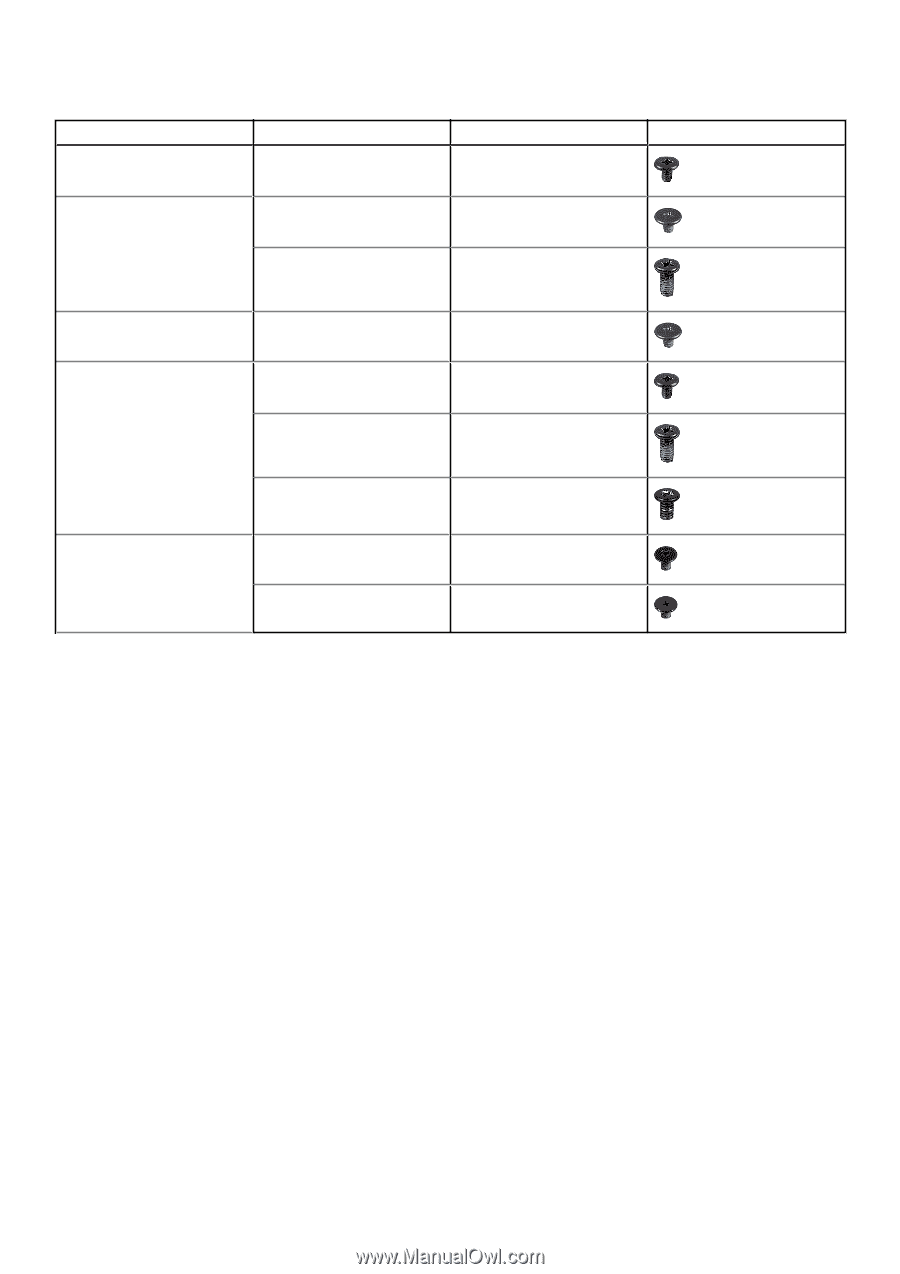
Table 1. Latitude 9510 screw list (continued)
Component
Screw type
Quantity
Image
M1.6x3.5
1
Power button
M1.5x2.5
3
M2.5x5
3
Fingerprint bracket
M1.5x2.5
3
System board
M1.6x3.5
9
M2.5x5
1
M1.6x4.5
1
Keyboard
M1.6x2
4
M1.6x1.5
36
Disassembly and reassembly
SIM card tray
Removing the SIM card tray
Prerequisites
Follow the procedure in
before working inside your computer
.
About this task
The following image provides a visual representation of the SIM card tray removal procedure.
Removing and Installing Components
13