Dell Latitude 9510 Service Manual
Dell Latitude 9510 Manual
 |
View all Dell Latitude 9510 manuals
Add to My Manuals
Save this manual to your list of manuals |
Dell Latitude 9510 manual content summary:
- Dell Latitude 9510 | Service Manual - Page 1
Latitude 9510 Service Manual Regulatory Model: P94F/P95F Regulatory Type: P94F001/P95F001 May 2020 Rev. A02 - Dell Latitude 9510 | Service Manual - Page 2
of data and tells you how to avoid the problem. WARNING: A WARNING indicates a potential for property damage, personal injury, or death. © 2020 Dell Inc. or its subsidiaries. All rights reserved. Dell, EMC, and other trademarks are trademarks of Dell Inc. or its subsidiaries. Other trademarks may be - Dell Latitude 9510 | Service Manual - Page 3
Contents Chapter 1: Working on your computer 5 Safety instructions...5 Before working inside your computer...5 Enter service mode...6 Safety precautions...7 Electrostatic discharge-ESD protection...7 ESD field service kit ...8 After working inside your computer...9 Chapter 2: Major components of - Dell Latitude 9510 | Service Manual - Page 4
POST Behavior...64 Virtualization Support options...64 Wireless screen options...64 Maintenance...65 System logs Deleting or changing an existing system setup password 68 Chapter 5: Troubleshooting...69 Dell SupportAssist Pre-boot System Performance Check diagnostics 69 Running the SupportAssist - Dell Latitude 9510 | Service Manual - Page 5
and the contacts. CAUTION: You should only perform troubleshooting and repairs as authorized or directed by the Dell technical assistance team. Damage due to servicing that is not authorized by Dell is not covered by your warranty. See the safety instructions that is shipped with the product or at - Dell Latitude 9510 | Service Manual - Page 6
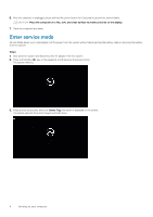
. CAUTION: Place the computer on a flat, soft, and clean surface to avoid scratches on the display. 7. Place the computer face down. Enter service mode Service Mode allows you to immediately cut the power from the system without disconnecting the battery cable or removing the battery from the system - Dell Latitude 9510 | Service Manual - Page 7
Service Mode, press the power button to power on the system. Safety precautions The safety precautions chapter details the primary steps to be taken before performing any disassembly instructions . Standby power Dell products with standby such as intermittent problems or a shortened product - Dell Latitude 9510 | Service Manual - Page 8
for safe transport. ESD protection summary It is recommended that all field service technicians use the traditional wired ESD grounding wrist strap and protective anti-static mat at all times when servicing Dell products. In addition, it is critical that technicians keep sensitive parts separate - Dell Latitude 9510 | Service Manual - Page 9
After working inside your computer About this task NOTE: Leaving stray or loose screws inside your computer may severely damage your computer. Steps 1. Replace all screws and ensure that no stray screws remain inside your computer. 2. Connect any external devices, peripherals, or cables you removed - Dell Latitude 9510 | Service Manual - Page 10
board 7. Smart card reader (optional) 8. Palmrest assembly 9. LCD panel 10. Keyboard 11. I/O board 12. System fan 13. Battery 14. Speaker NOTE: Dell provides a list of components and their part numbers for the original system configuration purchased. These parts are available according to warranty - Dell Latitude 9510 | Service Manual - Page 11
3 Removing and Installing Components Topics: • Recommended tools • Screw list • Disassembly and reassembly Recommended tools The procedures in this document may require the following tools: • Phillips #0 screwdriver • Phillips #1 screwdriver • Plastic scribe - Recommended for field technician - Dell Latitude 9510 | Service Manual - Page 12
screws are not left attached to such surface when replacing a component. NOTE: Screw color may vary with the configuration ordered. Table 1. Latitude 9510 screw list Component Screw type Base cover Captive screws Quantity 9 Image 4-cell battery 6-cell battery WWAN M1.6x3.5 1 M2x3 4 M1 - Dell Latitude 9510 | Service Manual - Page 13
Table 1. Latitude 9510 screw list (continued) Component Screw type M1.6x3.5 Power button M1.5x2.5 M2.5x5 Quantity 1 3 3 Fingerprint bracket M1.5x2.5 3 System board M1.6x3.5 9 M2.5x5 1 - Dell Latitude 9510 | Service Manual - Page 14
Steps 1. Insert a pin into the release hole to release the SIM card tray [1]. 2. Push the pin to disengage the lock, and eject the SIM card tray [2]. 3. Slide the SIM card tray out of the slot on the system [3]. Installing the SIM card tray Prerequisites If you are replacing a component, remove the - Dell Latitude 9510 | Service Manual - Page 15
Steps 1. Align and place the SIM card in the dedicated slot on the SIM card tray [1]. 2. Slide the SIM card tray into the slot in the system [2], and push it to lock in place [3]. Next steps Follow the procedure in After working on your computer. MicroSD card Removing the microSD card Prerequisites - Dell Latitude 9510 | Service Manual - Page 16
Steps 1. Push the microSD card to eject it from the slot [1]. 2. Remove the microSD card from the system [2]. Installing the microSD card Prerequisites If you are replacing a component, remove the existing component before performing the installation procedure. About this task The following image - Dell Latitude 9510 | Service Manual - Page 17
cover Removing the base cover Prerequisites 1. Follow the procedure in before working inside your computer. 2. Remove the microSD card. 3. Remove the SIM card tray. 4. Enter service mode. Removing and Installing Components 17 - Dell Latitude 9510 | Service Manual - Page 18
About this task 18 Removing and Installing Components - Dell Latitude 9510 | Service Manual - Page 19
Steps 1. Loosen the nine captive screws that secure the base cover to the system. 2. Using a plastic scribe, pry open the base cover starting from the recesses located in the U-shaped indents near the hinges at the top edge of the base cover. NOTE: Do not pull the base cover from the top side - Dell Latitude 9510 | Service Manual - Page 20
card Prerequisites 1. Follow the procedure in before working inside your computer. 2. Remove the microSD card. 3. Remove the SIM card tray. 4. Enter service mode. 5. Remove the base cover. About this task The following images indicate the location of the WWAN card and provide a visual representation - Dell Latitude 9510 | Service Manual - Page 21
Steps 1. Using a plastic scribe, pry open the WWAN card shield covering the WWAN card. 2. Loosen the single captive screw that secures the WWAN-card bracket to the WWAN card. 3. Lift the WWAN-card bracket out of the system. 4. Disconnect the antenna cables from the connectors on the WWAN card. 5. - Dell Latitude 9510 | Service Manual - Page 22
Steps 1. Align the notch on the WWAN card with the tab on the WWAN-card slot. 2. Slide the WWAN card at an angle into the WWAN-card slot. 3. Connect the antenna cables to the connectors on the WWAN card. 4. Align and place the WWAN-card bracket on the system board and WWAN card, and tighten the - Dell Latitude 9510 | Service Manual - Page 23
4. Enter service mode. 5. Remove the Base cover. About this task The following images indicate the location of the solid-state drive and provide a visual representation of the - Dell Latitude 9510 | Service Manual - Page 24
computer. Speakers Removing the speaker Prerequisites 1. Follow the procedure in before working inside your computer. 2. Remove the microSD card. 3. Remove the SIM card tray. 4. Enter service mode. 24 Removing and Installing Components - Dell Latitude 9510 | Service Manual - Page 25
adhesive tape that secures the battery cable to the system board. 2. Disconnect the speaker cable, and unroute the speaker cable from the routing guide. 3. Remove the four (M1.6x1.8) screws that secure the speakers, and remove the speakers from the system. Installing the speaker Prerequisites If you - Dell Latitude 9510 | Service Manual - Page 26
on the system. 2. Replace the four (M1.6x1.8) screws that secure the speakers to the system. 3. Route the speaker cables through the routing guide and connect the speaker cable to the connector. 4. Adhere the adhesive tape to secure the speaker cable. Next steps 1. Install the Base cover. 2. Install - Dell Latitude 9510 | Service Manual - Page 27
Remove the microSD card. 3. Remove the SIM card tray. 4. Enter service mode. 5. Remove the Base cover. About this task The following images 1. Disconnect the I/O cable and unroute the antenna cable through the routing guide. 2. Disconnect the system fan cable from the connector and peel the - Dell Latitude 9510 | Service Manual - Page 28
3. Connect the system fan cable and adhere the adhesive tape to secure the system fan cable. 4. Route the antenna cable through the routing guide, and connect the I/O cable. NOTE: Reconnect the battery after system repair. Next steps 1. Install the Speakers. 2. Install the Base cover. 3. Install the - Dell Latitude 9510 | Service Manual - Page 29
cable Prerequisites 1. Follow the procedure in before working inside your computer. 2. Remove the microSD card. 3. Remove the SIM card tray. 4. Enter service mode. 5. Remove the Base cover. About this task The following images indicate the location of the I/O daughter board power cable and provide - Dell Latitude 9510 | Service Manual - Page 30
I/O board Prerequisites 1. Follow the procedure in before working inside your computer. 2. Remove the microSD card. 3. Remove the SIM card tray. 4. Enter service mode. 5. Remove the Base cover. 6. Remove the System Fan. About this task The following image indicates the location of the I/O board and - Dell Latitude 9510 | Service Manual - Page 31
cable, and LED board cable from the I/O board. 2. Remove the four (M1.6x3.5) screws and lift the I/O board out of the laptop. Installing the I/O board Prerequisites If you are replacing a component, remove the existing component before performing the installation procedure. About this task The - Dell Latitude 9510 | Service Manual - Page 32
to the connectors on the I/O board. NOTE: Reconnect the battery cable after laptop repair is completed. Next steps 1. Install the System Fan. 2. Install the 2. Remove the microSD card. 3. Remove the SIM card tray. 4. Enter service mode. 5. Remove the Base cover. 6. Remove the Fan. 7. Remove the - Dell Latitude 9510 | Service Manual - Page 33
Steps 1. Remove the three M1.5x2.5 screws securing the fingerprint reader bracket. 2. Remove the power button bracket from the system. 3. Peel off the power button assembly from the palm rest and remove the power button assembly from the system. Installing the power button About this task The - Dell Latitude 9510 | Service Manual - Page 34
reader Prerequisites 1. Follow the procedure in before working inside your computer. 2. Remove the microSD card. 3. Remove the SIM card tray. 4. Enter service mode. 5. Remove the Base cover. 6. Remove the system fan. 7. Remove the I/O board . About this task The following images indicate the - Dell Latitude 9510 | Service Manual - Page 35
2. Rotate and lift the hinges up to remove the hinges. 3. Remove the three (M1.5x2.5) screws securing the fingerprint bracket in place. 4. Remove the fingerprint reader bracket from the system. 5. Peel off the power button with the fingerprint reader assembly from the sponge on the palm rest, and - Dell Latitude 9510 | Service Manual - Page 36
to pry on or against the battery. • Ensure any screws during the servicing of this product are not lost or misplaced, to prevent accidental puncture or damage Dell technical support for assistance. See www.dell.com/contactdell. • Always purchase genuine batteries from www.dell.com or authorized Dell - Dell Latitude 9510 | Service Manual - Page 37
. Technicians must be careful when unrouting the antenna cables from their routing guides while they are still attached to the wireless card. 2. Remove the left side of the system, and remove the battery from the laptop. Installing the 4-cell battery Prerequisites If you are replacing a component - Dell Latitude 9510 | Service Manual - Page 38
Steps 1. Align and place the battery from the left side on the laptop. 2. Replace the single (M1.6x3.5) screw and four (M2x3) screws to secure the battery in place. 3. Route the wireless antenna cables on the routing guides and adhere the adhesive tape. Next steps 1. Install the Speakers. 2. Install - Dell Latitude 9510 | Service Manual - Page 39
If battery was disconnected from system board for service, there will be a delay during system when unrouting the antenna cables from their routing guides while they are still attached to the wireless card side and remove the battery from the laptop. Installing the 6-cell battery About this task - Dell Latitude 9510 | Service Manual - Page 40
NOTE: If battery was disconnected from system board for service, there will be a delay during system boot-up as the system will undergo RTC battery reset. Steps 1. Align and place the battery from the left side on the laptop. 2. Install the single (M1.6x3.5) screw and eight (M2x3) screws to secure - Dell Latitude 9510 | Service Manual - Page 41
About this task Steps 1. Open the latch and disconnect the touchpad FPC from the system board. 2. Open the latch and disconnect the smart card reader cable from the I/O-daughter board. 3. Remove the two screws (M2x2) that secure the smart card reader to the palmrest assembly. 4. Lift the smart card - Dell Latitude 9510 | Service Manual - Page 42
About this task Steps 1. Align and place the smart card reader on the palmrest assembly. 2. Replace the two screws (M2x2) to secure the smart card reader to the palmrest assembly. 3. Connect the smart card reader cable to the connector on the I/O-daughter board and close the latch. 4. Connect the - Dell Latitude 9510 | Service Manual - Page 43
System board Removing the system board Prerequisites 1. Follow the procedure in before working inside your computer. 2. Remove the microSD card. 3. Remove the SIM card tray. 4. Remove the Base cover. 5. Remove the Solid-state drive. 6. Remove the WWAN. 7. Remove the Battery. 8. Remove the Speakers. - Dell Latitude 9510 | Service Manual - Page 44
Steps 1. Remove the single (M1.6x3.5) screw that secures the display-cable bracket to the system board. Push the display-cable bracket from the bottom edge, and rotate the bracket in a counterclockwise direction to release the bracket from the securing peg, and remove it from the system. 2. - Dell Latitude 9510 | Service Manual - Page 45
board. 5. Disconnect the Darwin antenna cables from the wireless module, and unroute the cables from the routing guides on the system board. 6. Unroute the WWAN antenna cable from the routing guides on the system board. 7. Remove the two (M1.6x4.5) screws that secure the two system board hooks - Dell Latitude 9510 | Service Manual - Page 46
46 Removing and Installing Components - Dell Latitude 9510 | Service Manual - Page 47
. 8. Route the WWAN antenna cable through the routing guides on the system board. 9. Connect the Darwin antenna cables to the wireless module , and route the cables through the routing guides on the system board. 10. Align and place the wireless module bracket - Dell Latitude 9510 | Service Manual - Page 48
the location of the display assembly and provide a visual representation of the removal procedure. NOTE: The display assembly removal procedure is the same for both laptop and convertible chassis. 48 Removing and Installing Components - Dell Latitude 9510 | Service Manual - Page 49
Removing and Installing Components 49 - Dell Latitude 9510 | Service Manual - Page 50
, remove the existing component before performing the installation procedure. NOTE: The display assembly installation procedure is the same for both laptop and convertible chassis. About this task The following image indicates the location of the display assembly and provides a visual representation - Dell Latitude 9510 | Service Manual - Page 51
Removing and Installing Components 51 - Dell Latitude 9510 | Service Manual - Page 52
and place the system chassis under the hinges of the display assembly. 2. Install the six (M2.5x5) screws that secure the display hinges to the laptop. 3. Connect the display cable to the system board. Connect and adhere the camera cable to the system board. 4. Place the display cable bracket in - Dell Latitude 9510 | Service Manual - Page 53
4. Remove the Base cover. 5. Remove the Solid-state drive. 6. Remove the Speakers. 7. Remove the Battery. 8. Remove the Display assembly. 9. Remove the Fan. 10. Remove the I/O board . 11. Remove the System board. About this task The following images indicate the location of the keyboard and provide - Dell Latitude 9510 | Service Manual - Page 54
Installing the keyboard Prerequisites If you are replacing a component, remove the existing component before performing the installation procedure. About this task The following image indicates the location of the keyboard and provides a visual representation of the installation procedure. Steps 1. - Dell Latitude 9510 | Service Manual - Page 55
3. Install the Fan. 4. Install the Display assembly. 5. Install the Battery. 6. Install the Speakers. 7. Install the Solid-state drive. 8. Install the Base cover. 9. Install the SIM card tray 10. Install the microSD card. 11. Follow the procedure in After working on your computer . Palmrest assembly - Dell Latitude 9510 | Service Manual - Page 56
Installing the palmrest assembly Prerequisites If you are replacing a component, remove the existing component before performing the installation procedure. About this task The following image indicates the location of the palmrest assembly and provides a visual representation of the installation - Dell Latitude 9510 | Service Manual - Page 57
button to turn on your tablet. 2. Press and hold the Volume Up button when the Dell logo appears on the screen. 3. When the F12 boot selection menu appears, select BIOS Displays BIOS Version, Service Tag, Asset Tag, Ownership Tag, Ownership Date, Manufacture Date, and the Express Service Code. • - Dell Latitude 9510 | Service Manual - Page 58
and available for OS. If USB port is disabled, the OS cannot see any device attached to this port. The options are: • Enable USB Boot Support-enabled by default • Enable External USB Port-enabled by default NOTE: USB keyboard and mouse always work in the BIOS setup irrespective of these settings - Dell Latitude 9510 | Service Manual - Page 59
is disabled by default. • Enable SMART Reporting USB Configuration This is an optional feature. This field configures the integrated USB controller. If Boot Support is enabled, the system is allowed to boot any type of USB Mass Storage Devices (HDD, memory key, floppy). If USB port is enabled - Dell Latitude 9510 | Service Manual - Page 60
attached to this port. The options are: • Enable USB Boot Support • Enable External USB Port NOTE: Both the option is enabled by default. Dell Type-C dock configuration Thunderbolt Adapter configuration: Does not support this configuration Allows you to configure the Thunderbolt™ adapter security - Dell Latitude 9510 | Service Manual - Page 61
Option Description • 30 seconds • 1 minute • 5 minute • 15 minute • never Touchscreen Does not support this option Unobtrusive Mode Allows you to select the option. When enabled, pressing Fn+F7 turns off all light and sound emissions in the system. - Dell Latitude 9510 | Service Manual - Page 62
stored in the TPM. Changes to this setting take effect immediately. Absolute (R) Allows you to activate or disable the optional Computrace Service from Absolute software. The options are: • Deactivate • Disable • Activate NOTE: The Activate and Disable options will permanently activate or disable - Dell Latitude 9510 | Service Manual - Page 63
The performance of some applications improves with the additional cores. This option is enabled by default. Allows you to enable or disable multi-core support for the processor. • AllThis option is enabled by default. •1 •2 •3 Allows you to enable or disable the Intel SpeedStep mode of the processor - Dell Latitude 9510 | Service Manual - Page 64
Prompt on Warnings and Errors. This option is enabled by default. Continue on Warnings Sign of Life Indication Virtualization Support options Option Description Virtualization Allows you to enable or disable the Intel Virtualization Technology. Enable Intel Virtualization Technology This option - Dell Latitude 9510 | Service Manual - Page 65
on the outer box or the WWAN card. Maintenance Option Service Tag Asset Tag BIOS Downgrade Data Wipe BIOS Recovery Description Displays the Service Tag of your computer. Allows you to create a system outlet. Steps 1. Restart the tabletnotebookdesktop. 2. Go to Dell.com/support. System setup 65 - Dell Latitude 9510 | Service Manual - Page 66
instructions on screen. 4. If you are unable to locate or find the Service Tag, click the Product Category of your tabletnotebookdesktop. 5. Choose the Product Type from the list. 6. Select your tabletnotebookdesktop model and the Product Support press F12 when the Dell splash logo appears to - Dell Latitude 9510 | Service Manual - Page 67
Figure 1. DOS BIOS Update Screen System and setup password Table 2. System and setup password Password type System password Setup password Description Password that you must enter to log on to your system. Password that you must enter to access and make changes to the BIOS settings of your - Dell Latitude 9510 | Service Manual - Page 68
• The password can contain the numbers 0 through 9. • Only lower case letters are valid, upper case letters are not allowed. • Only the following special characters are allowed: space 3. Type the system password that you entered earlier in the Confirm new password field and click OK. 4. Press Esc - Dell Latitude 9510 | Service Manual - Page 69
Troubleshooting Topics: • Dell SupportAssist Pre-boot System Performance Check diagnostics • System diagnostic lights • Flashing BIOS (USB key) • Flashing the BIOS • Backup media and recovery options • WiFi power cycle • Flea power release Dell inform you of problems encountered during testing NOTE - Dell Latitude 9510 | Service Manual - Page 70
table shows different power and battery-status light patterns and associated problems. Table 3. LED codes Diagnostic light codes 2,1 Problem description Processor failure 2,2 System board: BIOS or ROM (Read "Flashing the BIOS" to download the latest BIOS setup program file. 70 Troubleshooting - Dell Latitude 9510 | Service Manual - Page 71
-click the BIOS update file icon and follow the instructions on the screen. Backup media and recovery options It is recommended to create a recovery drive to troubleshoot and fix problems that may occur with Windows. Dell proposes multiple options for recovering Windows operating system on your - Dell Latitude 9510 | Service Manual - Page 72
even after it has been powered off and the battery has been removed. The following procedure provides the instructions on how to conduct flea power release: Steps 1. Turn off your computer. 2. Disconnect the power the power adapter to your computer. 5. Turn on your computer. 72 Troubleshooting - Dell Latitude 9510 | Service Manual - Page 73
. Availability varies by country and product, and some services may not be available in your area. To contact Dell for sales, technical support, or customer service issues: Steps 1. Go to Dell.com/support. 2. Select your support category. 3. Verify your country or region in the Choose a Country
-
 1
1 -
 2
2 -
 3
3 -
 4
4 -
 5
5 -
 6
6 -
 7
7 -
8
-
9
-
10
-
11
-
12
-
13
-
14
-
15
-
16
-
17
-
18
-
19
-
20
-
21
-
22
-
23
-
24
-
25
-
26
-
27
-
28
-
29
-
30
-
31
-
32
-
33
-
34
-
35
-
36
-
37
-
38
-
39
-
40
-
41
-
42
-
43
-
44
-
45
-
46
-
47
-
48
-
49
-
50
-
51
-
52
-
53
-
54
-
55
-
56
-
57
-
58
-
59
-
60
-
61
-
62
-
63
-
64
-
65
-
66
-
67
-
68
-
69
-
70
-
71
-
72
-
73
 |
 |

Latitude 9510
Service Manual
Regulatory Model: P94F/P95F
Regulatory Type: P94F001/P95F001
May 2020
Rev. A02