2010 Yamaha Motorsports RS Vector GT Owners Manual - Page 78
2010 Yamaha Motorsports RS Vector GT Manual

Page 78 highlights
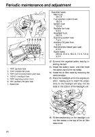
Periodic maintenance and adjustment Specified fuses: Main fuse: 40.0 A Fuel injection system fuse: 10.0 A Ignition fuse: 15.0 A Radiator fan fuse: 5.0 A Headlight fuse: 20.0 A Signaling system fuse: 7.5 A Auxiliary DC jack fuse: 3.0 A Helmet shield heater jack fuse: 3.0 A Spare fuses: 20.0 A, 15.0 A, 10.0 A, 7.5 A, 5.0 A, 3.0 A 12. Connect the negative battery lead by installing the bolt. 13. Install the battery cover, and then hook the battery band onto the holder. 14. Install the air filter case by reversing the removal steps. 15. Place the headlight unit in the original position, making sure to insert the projections on the headlight unit stay into the slots on the bottom of the headlight unit. 12 3 4 5 6 7 1. 2. 3. 4. 5. 6. 7. "IGN" (ignition) fuse "FAN" (radiator fan) fuse "S/H" (helmet shield heater jack) fuse "HEAD" (headlight) fuse "SIG" (signaling system) fuse "DC" (auxiliary DC jack) fuse Spare fuse 16. Fit the weatherstrip on the headlight unit into the recess in the top of the air filter case cover. 72
-
 1
1 -
2
-
3
-
4
-
5
-
6
-
7
-
8
-
9
-
10
-
11
-
12
-
13
-
14
-
15
-
16
-
17
-
18
-
19
-
20
-
21
-
22
-
23
-
24
-
25
-
26
-
27
-
28
-
29
-
30
-
31
-
32
-
33
-
34
-
35
-
36
-
37
-
38
-
39
-
40
-
41
-
42
-
43
-
44
-
45
-
46
-
47
-
48
-
49
-
50
-
51
-
52
-
53
-
54
-
55
-
56
-
57
-
58
-
59
-
60
-
61
-
62
-
63
-
64
-
65
-
66
-
67
-
68
-
69
-
70
-
71
-
72
-
 73
73 -
 74
74 -
 75
75 -
 76
76 -
 77
77 -
 78
78 -
 79
79 -
 80
80 -
 81
81 -
 82
82 -
 83
83 -
84
-
85
-
86
-
87
-
88
-
89
-
90
-
91
-
92
-
93
-
94
-
95
-
96
-
97
-
98
 |
 |
