Invacare M94 Owners Manual
Invacare M94 Manual
 |
View all Invacare M94 manuals
Add to My Manuals
Save this manual to your list of manuals |
Invacare M94 manual content summary:
- Invacare M94 | Owners Manual - Page 1
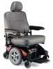
Owner's Operator and Maintenance Manual Pronto® M94™ with SureStep® DEALER: This manual MUST be given to the user of the product. USER: BEFORE using this product, read this manual and save for future reference. For more information regarding Invacare products, parts, and services, please visit www. - Invacare M94 | Owners Manual - Page 2
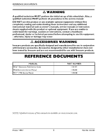
for use with Invacare products. REFERENCE DOCUMENTS MANUAL MK6i™Electronics Field Service Guide MK6i Electronics Service Manual M91™/ M94 Service Manual PART NUMBER 1141471 1143203 1125038 NOTE: Updated versions of this manual are available on www.invacare.com. Pronto® M94™ 2 Part No 1122145 - Invacare M94 | Owners Manual - Page 3
Weekly...24 Inspect/Adjust Monthly...24 Inspect/Adjust Periodically...24 Troubleshooting - Mechanical ...25 Troubleshooting - Electrical...25 SPJ+, SPJ+ w/PSS or SPJ+ w/ACC Joysticks 25 MPJ+, PSR+, PSF+ Joysticks or Displays 27 Checking Battery Charge Level...29 Part No 1122145 3 Pronto® M94™ - Invacare M94 | Owners Manual - Page 4
the Wheelchair...30 Turning the Power On/Off ...30 Using the Joystick to Drive the Wheelchair 31 SPJ+, MK6i SPJ+ w/PSS and MK6i SPJ+ w/ACC Joystick Switches and Indicators 32 On/Off Button ...32 Speedometer ...32 Speed Control Buttons...33 Joystick...33 Charger/Programming Input...33 Service - Invacare M94 | Owners Manual - Page 5
60 Model PHWH93 ...60 Model PH904A and PHAL4A...60 Replacing Heel Loops ...61 Raising/Lowering Elevating Front Riggings 61 Adjusting/Replacing Telescoping Front Rigging Supports - Van Style Seats 61 Adjusting/Replacing Telescoping Front Rigging Supports - ASBA 63 Part No 1122145 5 Pronto® M94™ - Invacare M94 | Owners Manual - Page 6
ONLINE at warranty.invacare.com Please have your model number and purchase date available to complete your registration. Any registration information you submit will only be used by Invacare Corporation and protected as required by applicable laws and regulations. Pronto® M94™ 6 Part No 1122145 - Invacare M94 | Owners Manual - Page 7
Signal words are used in this manual and apply to hazards or unsafe SUBJECT TO CHANGE WITHOUT NOTICE. WHEELCHAIR USER As a manufacturer of wheelchairs, Invacare endeavors to supply a wide variety of wheelchairs to meet many needs of the MUST be replaced immediately. Part No 1122145 7 Pronto® M94™ - Invacare M94 | Owners Manual - Page 8
different from other chairs previously used. This Power Wheelchair has Invacare's SureStep technology, a feature that provides the chair with optimum traction attempting active use of this wheelchair. Other general warnings listed within this document also apply. Pronto® M94™ 8 Part No 1122145 - Invacare M94 | Owners Manual - Page 9
LABEL LOCATIONS LABEL LOCATIONS NOTE: The serial number label is located on the inside of the right rear frame. Part No 1122145 9 Pronto® M94™ - Invacare M94 | Owners Manual - Page 10
their wheelchair. Refer to When to Charge Batteries on page 98 for more information about the battery discharge indicator. **NOTE: Refer to Stability and Balance on page 17. Footnotes: 1. Back height without headrest. 2. Includes seating systems and accessories. Pronto® M94™ 10 Part No 1122145 - Invacare M94 | Owners Manual - Page 11
weight in the opposite direction of the turn may cause the inside drive wheel to lose traction and the wheelchair to tip over. The arms on the M94 wheelchair are designed as armrests ONLY. The arms are not designed to support the full weight of the wheelchair user. Part No 1122145 11 Pronto® M94™ - Invacare M94 | Owners Manual - Page 12
aircraft safety belts. If signs of wear appear, belt MUST be replaced immediately. Make sure the detent balls of the quick‐release pin are fully released beyond the outer edge of the tube before operating the wheelchair. Otherwise, injury and/or damage may result. Pronto® M94™ 12 Part No 1122145 - Invacare M94 | Owners Manual - Page 13
contained in this manual are based on the use of deep cycle gel cell or sealed lead acid batteries. Invacare strongly recommends their use as the power source for this unit. Carefully read battery/battery charger information prior to installing, servicing or operating your wheelchair. The use of - Invacare M94 | Owners Manual - Page 14
tested as a seat for any kind of weight training. If occupant uses said wheelchair as a weight training apparatus, Invacare shall not be liable for bodily injury and the warranty is void. Weight Limitation The M94 with SureStep has a weight limitation of 500 lbs. Pronto® M94™ 14 Part No 1122145 - Invacare M94 | Owners Manual - Page 15
radios, and cellular phones. The interference (from radio wave sources) can cause the powered wheelchair to release its brakes, move by itself, or move in unintended directions. It can far as we know, are not likely to cause EMI problems to your powered wheelchair. Part No 1122145 15 Pronto® M94™ - Invacare M94 | Owners Manual - Page 16
or turn ON personal communication devices, such as cellular phones, while the powered wheelchair is turned ON; 2) Be aware of nearby transmitters, such as radio electronics of this wheelchair as manufactured by Invacare may adversely affect the EMI immunity levels. Pronto® M94™ 16 Part No 1122145 - Invacare M94 | Owners Manual - Page 17
only as a "basic" guide. The techniques that are discussed on the following pages have been used successfully by many. Individual wheelchair users often develop skills to deal with daily living activities that may differ from those described in this manual. Invacare recognizes and encourages each - Invacare M94 | Owners Manual - Page 18
a problem. The chair cannot reverse over the bump at this point. Continue forward and then turn around. While the M94 is wheelchair to feel unstable. CAUTION Be aware of condition of ramp. Traction will be diminished/nonexistent on a slippery surface. Proceed with caution. Pronto® M94™ 18 Part - Invacare M94 | Owners Manual - Page 19
move an unoccupied power wheelchair up or down the stairs. Invacare recommends using two assistants and making thorough preparations. Use ONLY secure, nondetachable parts for hand-hold supports. It is strongly recommended to lift the wheelchair only by the rear frame and the front forks - otherwise - Invacare M94 | Owners Manual - Page 20
to move a wheelchair between floors. Serious bodily injury may occur. Ensure that driving surface, ramps, lifts, elevators, etc. are capable of supporting combined weight of user and wheelchair (for a 500lbs user, the combined weight could be up to 800 lbs). Pronto® M94™ 20 Part No 1122145 - Invacare M94 | Owners Manual - Page 21
wheelchair power off and engage the Motor Release Levers to prevent the wheels from moving before attempting to transfer in or out of the wheelchair. Also, make sure every precaution is taken to reduce the gap distance by aligning both the front wheelchair wheelchair wheelchair Position the front and - Invacare M94 | Owners Manual - Page 22
wheelchair as close as possible to the desired object. Point the front and rear casters rearward to create the longest possible wheelbase. Reach back only as far as your arm will extend without changing your sitting position. FIGURE 3.5 Reaching and Bending - Backward Pronto® M94™ 22 Part - Invacare M94 | Owners Manual - Page 23
TROUBLESHOOTING NOTE: Every six months or as necessary take your wheelchair to a qualified dealer for a thorough inspection and servicing. Regular cleaning will reveal loose or worn parts and enhance the smooth operation of your wheelchair are free of debris. Part No 1122145 23 Pronto® M94™ - Invacare M94 | Owners Manual - Page 24
SECTION 4-SAFETY INSPECTION/TROUBLESHOOTING Inspect/Adjust Weekly ❑ Ensure the seat is secured to wheelchair frame. ❑ Ensure the seat and/or back upholstery have no rips and DO NOT sag. seat and/or back upholstery have no rips and DO NOT sag. Replace if necessary. Pronto® M94™ 24 Part No 1122145 - Invacare M94 | Owners Manual - Page 25
- Electrical NOTE: For additional troubleshooting information and explanation of error codes, refer to the individual Electronics Manual supplied with each wheelchair SPJ+, SPJ+ w/PSS or SPJ+ w/ACC Joysticks The joystick information gauge and the service indicator give indications of the type - Invacare M94 | Owners Manual - Page 26
to make sure joystick is connected properly. Contact Invacare/Dealer for service. Contact Invacare/Dealer for service. Contact Invacare/Dealer for service. Contact Invacare/Dealer for service. Wrong type of remote connected. Contact Invacare/Dealer for service. Pronto® M94™ 26 Part No 1122145 - Invacare M94 | Owners Manual - Page 27
be used to drive the chair (Error code W05). This is normal behavior. Batteries draw excessive current when charging. Battery failure. Have batteries checked for shorted cell. Replace if necessary. Electrical malfunction. Contact Dealer/Invacare for service. Part No 1122145 27 Pronto® M94™ - Invacare M94 | Owners Manual - Page 28
to commands. Power indicator Off - even after recharging. Controller programmed improperly. Poor battery terminal connection. Electrical malfunction. Contact Dealer/Invacare to have controller reprogrammed. Have terminals cleaned. Contact Dealer/Invacare for Service. Pronto® M94™ 28 Part No - Invacare M94 | Owners Manual - Page 29
and safety. DON'T DO Don't perform any installation or maintenance without first reading this manual. Read and understand this manual and any service information that accompanies a battery and charger before operating the wheelchair. Don't perform installation or maintenance of bat- Move the - Invacare M94 | Owners Manual - Page 30
the power Off can be achieved by performing one of the following steps:. JOYSTICK ACTION MPJ+ Move the On/Off switch Back to the Off position. SPJ+ Press the On/Off button. SPJ+ Joysticks On/Off Button MPJ+ Joystick On/Off Switch FIGURE 5.1 Turning the Power On/Off Pronto® M94™ 30 Part - Invacare M94 | Owners Manual - Page 31
control knob to the appropriate setting. 2. Turn the power On. Refer to Turning the Power On/Off on page 30. 3. Maneuver the joystick in the following manner: MOVEMENT ACTION FORWARD Push joystick forward, towards the front of the wheelchair. REVERSE Pull joystick back, towards the rear of - Invacare M94 | Owners Manual - Page 32
) Additional Input for Powered Seating Switch Service Indicator *NOTE: The mode button is only present on SPJ+ w/ACC joystick. DETAIL "A" - FRONT VIEW Charger/ Programming Input when the seat has been elevated and the wheelchair is required to drive at 20% speed. Pronto® M94™ 32 Part No 1122145 - Invacare M94 | Owners Manual - Page 33
is located at the front of the joystick housing. This provides easy access for charging the wheelchair batteries. This port also serves as the Remote Programmer Communication connection. Driving is prevented while the system is charging. Service Indicator The AMBER service indicator will light when - Invacare M94 | Owners Manual - Page 34
front of the joystick housing and provides the following information to the user on the status of the wheelchair: 1. Power is On. 2. True state‐of‐battery‐charge, including notification of when the battery toggle up and release one more time to select DRIVE 1 ( ). Pronto® M94™ 34 Part No 1122145 - Invacare M94 | Owners Manual - Page 35
while the system is charging. LCD Display Screens The LCD Display is located in front of the joystick and provides information on the status of the wheelchair through a backlit display. The LCD display is readable in both bright sunlight and complete darkness. Part No 1122145 35 Pronto® M94™ - Invacare M94 | Owners Manual - Page 36
. *NOTE: Drive names can be customized. Actual drive names may display differently. This symbol shows the Battery Level and will change depending on the available battery power. This indicator is shown on every screen. This area displays status or instructions. Pronto® M94™ 36 Part No 1122145 - Invacare M94 | Owners Manual - Page 37
the operator issues a drive command and the Drive Icon on the main screen was highlighted. NOTE: The Drive's name, warning/info message, status icon and battery indicator are displayed on this screen. FIGURE 5.7 LCD Display Screens - Driving Screen Part No 1122145 37 Pronto® M94™ - Invacare M94 | Owners Manual - Page 38
chair. ICON DESCRIPTION 4-Switch Attendant Control RIM Control ECU (1 to 4) Proportional Attendant Control Compact Joystick Sip and Puff Control ASL Digital Control ASL Analog Control Shark Power The remote stop switch is used to stop the wheelchair. Remote Mode (Reset) Switch The remote mode - Invacare M94 | Owners Manual - Page 39
Mode* • Tilt/Recline Mode* • Information Center Display Selection (does not require Reset activation at power up) If any of the above modes are selected, the control will require activation of the memory card for saving or reading wheelchair parameters. Part No 1122145 39 Pronto® M94™ - Invacare M94 | Owners Manual - Page 40
lever to release the joystick mounting tube from the mounting bracket. 2. Remove the joystick from the wheelchair. 3. Remove the three hex screws that secure both halves of the mounting bracket to the arm secure the joystick mounting tube into the mounting bracket. Pronto® M94™ 40 Part No 1122145 - Invacare M94 | Owners Manual - Page 41
to release the joystick mounting tube from the mounting bracket. 2. Remove the joystick from the wheelchair. 3. Remove the three hex mounting screws, spacers and locknuts that secure the mounting bracket adjustment lock to tube by turning lever on adjustment lock. Part No 1122145 41 Pronto® M94™ - Invacare M94 | Owners Manual - Page 42
5-WHEELCHAIR joystick connector with one hand and the controller connector on the wheelchair in the other and disconnect them by pulling them apart. Connecting the joystick connector with one hand and the controller connector on the wheelchair in the other and align them. 2. Lightly push to engage - Invacare M94 | Owners Manual - Page 43
SECTION 5-WHEELCHAIR OPERATION MPJ+ Joysticks NOTE: For this procedure, refer to FIGURE 5.13. Disconnecting 1. Pull the latch away from other connectors. Joystick Connector Latch Other Connectors FIGURE 5.13 Disconnecting/Connecting the Joysticks - MPJ+ Joysticks Part No 1122145 43 Pronto® M94™ - Invacare M94 | Owners Manual - Page 44
position (FIGURE 6.1). 2. Remove the quick release pin that secures the flip back armrest to the wheelchair frame. 3. Pull Up on the flip back armrest and remove the armrest from the arm sockets. 4. Repeat STEPS 1‐3 for the opposite flip back armrest, if necessary. Pronto® M94™ 44 Part No 1122145 - Invacare M94 | Owners Manual - Page 45
is locked in place. 5. Repeat STEPS 1‐4 for opposite flip back armrest, if necessary. Adjusting 1. Unlock top of flip back armrest by pulling height adjustment lever into the Up (horizontal) position. 2. Adjust top of the flip back armrest to the desired height. Part No 1122145 45 Pronto® M94™ - Invacare M94 | Owners Manual - Page 46
flip back armrest to make sure the armrest is locked in place. 5. Repeat STEPS 1‐4 for opposite flip back armrest, if necessary. Height Adjustment Lever Flip Back Armrest Release Lever Locked (Down - Vertical) Flip Back Armrest Front Pronto® M94™ 46 Part No 1122145 - Invacare M94 | Owners Manual - Page 47
SECTION 6-ARMS Armrest Detail "A" - Angle Adjustment Screw Detail "B" - Height Height Adjustment Holes Jam Nut Pinch Point Lock Knob FIGURE 6.3 Adjusting Van Seat Armrests Armrest Seat Frame Assembly Part No 1122145 47 Pronto® M94™ - Invacare M94 | Owners Manual - Page 48
service and before use, make sure that all attaching hardware is tightened securely - otherwise injury or damage may result. Before performing any maintenance, adjustment or service release tab towards the inside of the chair. Lower headrest to desired position. Pronto® M94™ 48 Part No 1122145 - Invacare M94 | Owners Manual - Page 49
inside of wheelchair to Front Top Bottom 85° Top Rear Bottom Front Top Bottom 90° Top Rear Bottom Front Top Bottom 95° Top Rear Bottom Front 100° Top Bottom Top Rear Bottom Front FIGURE 7.3 Adjusting the Back Angle - Adjustable Seat Back Angle (ASBA) Model Part No 1122145 49 Pronto® M94 - Invacare M94 | Owners Manual - Page 50
Position the seat in the rear pivot brackets as shown in FIGURE 7.4. 2. Tilt front edge of seat down. 3. When seat is lowered, engage seat brackets into seat clevis Latch Bar (located under the front of the seat) FIGURE 7.4 Removing/Installing the Seat Assembly Pronto® M94™ 50 Part No 1122145 - Invacare M94 | Owners Manual - Page 51
would cause the front riggings of the wheelchair to interfere with other components of the chair. 4. Reinstall mounting screw and locknut (FIGURE 7.5). Securely tighten. 5. Repeat STEPS 2‐4 for the seat. Refer to Removing/Installing the Seat Assembly on page 50. Part No 1122145 51 Pronto® M94™ - Invacare M94 | Owners Manual - Page 52
Support Tube Front STEP 4 with the seat frame mounting holes determined in STEP 4. 6. Using the four mounting screws and washers, secure the seat assembly to the seat frame. Securely tighten. 7. Reinstall the seat. Refer to Removing/Installing the Seat Assembly on page 50. Pronto® M94™ 52 Part - Invacare M94 | Owners Manual - Page 53
Seat Position Use these Mounting Holes for Standard Seat Position * DO NOT Use Bottom View of Seat Assembly Front of Seat DO NOT Use these mounting holes. * DO NOT Use Use these Mounting Holes for 1-inch under the seat that secure the seat back assembly in place. Part No 1122145 53 Pronto® M94™ - Invacare M94 | Owners Manual - Page 54
"A" of FIGURE 7.7 for proper seat depth positions. For example, to achieve maximum seat depth, the front mounting hole on the seat back bracket aligns with the third hole on the seat base. 5. Reinstall the seat pan and seat positioning straps to the seat frame. Pronto® M94™ 54 Part No 1122145 - Invacare M94 | Owners Manual - Page 55
straps to the seat frame. Securely tighten. Seat Assembly Seat Positioning Strap Seat Frame Rear of Seat Frame Washer Front of Seat Frame Seat Positioning Strap Mounting Screws Seat Rail FIGURE 7.9 Replacing the Seat Positioning Strap - Van Seat Model Part No 1122145 55 Pronto® M94™ - Invacare M94 | Owners Manual - Page 56
operating the wheelchair. Otherwise, injury and/or damage may result. Keep detent balls clean. 1. Position the footboard assembly onto the wheelchair frame so that the mounting hole in the wheelchair frame aligns with the desired mounting hole in the footboard assembly. Pronto® M94™ 56 Part No - Invacare M94 | Owners Manual - Page 57
the pin in. Make sure the detent balls are fully released beyond the outer edge of the tube (Detail "A" of FIGURE 8.3). Mounting Hole Wheelchair Frame Detail "A" - Screw, Washer and Jam Nut Footboard Assembly Part No 1122145 FIGURE 8.2 Adjusting the Footboard Assembly - Angle 57 Pronto® M94™ - Invacare M94 | Owners Manual - Page 58
to the wheelchair frame. ƽ WARNING Make sure the detent Wheelchair Frame Detail "A" - Bottom View of Footboard Quick Release Pin Quick Release Pin Detent Ball Footboard Assembly Outer Edge of Tube Detent Balls FIGURE 8.3 Adjusting the Footboard Assembly - Depth Pronto® M94™ 58 Part - Invacare M94 | Owners Manual - Page 59
Installing/Removing Front Riggings 4. Push the front rigging towards the inside of the wheelchair until it locks into place. NOTE: The footplate will be on the inside of the wheelchair when locked in place. 5. Repeat STEPS 1‐4 for opposite side of wheelchair. Part No 1122145 59 Pronto® M94™ - Invacare M94 | Owners Manual - Page 60
lower footrest to footrest support. Tighten securely. FIGURE 9.2 Adjusting Footrest Height Model PHWH93 6. Repeat STEPS 1‐5 for the opposite side of the wheelchair footrest, if necessary. 7. Reinstall the footrest(s) onto the wheelchair. Refer to Installing/Removing Front Riggings on page 59 - Invacare M94 | Owners Manual - Page 61
FIGURE 9.5 Raising/Lowering Elevating Front Riggings Adjusting/Replacing Telescoping Front Rigging Supports - Van Style Seats NOTE: When adjusting the telescoping front rigging support depth, ensure the footplate does not interfere with the caster wheel rotation. Part No 1122145 61 Pronto® M94™ - Invacare M94 | Owners Manual - Page 62
and locknuts, secure the telescoping front rigging support to the seat frame as shown in FIGURE 9.6. 5. If necessary, repeat STEPS 2‐4 on remaining telescoping front rigging support. 6. Reinstall the seat. Refer to Removing/Installing the Seat Assembly on page 50. Pronto® M94™ 62 Part No 1122145 - Invacare M94 | Owners Manual - Page 63
front rigging. 3. Secure telescoping front rigging at desired depth with existing two mounting screws, spacers, and locknuts. Securely tighten. NOTE: The two telescoping front rigging supports can be positioned at different depths depending on the need of the user. Part No 1122145 63 Pronto® M94 - Invacare M94 | Owners Manual - Page 64
SECTION 9-FRONT RIGGINGS Mounting Screws Spacer Locknut Telescoping Front Tube Spacer Locknut FIGURE 9.7 Adjusting/Replacing Telescoping Front Rigging Supports - ASBA Pronto® M94™ 64 Part No 1122145 - Invacare M94 | Owners Manual - Page 65
service and before use, make sure that all attaching hardware is tightened securely - otherwise injury or damage may result. Before performing any maintenance, adjustment or service of the wheelchair. Removing/Installing "A" of FIGURE 10.1. • Front Shroud ‐ Position front shroud onto the two base - Invacare M94 | Owners Manual - Page 66
FRONT SHROUD Base Frame Hooks Rear of Wheelchair Base Frame Seat Supports Hook and Loop Strips Front of Wheelchair Release Knob FIGURE 10.1 Removing/Installing the Shrouds Front center of the wheelchair (drive position) as shown in Detail "A" of FIGURE 10.2. Pronto® M94™ 66 Part No 1122145 - Invacare M94 | Owners Manual - Page 67
Wheelchair Towards Center of Wheelchair Motor Locks Disengaged (Freewheel Mode) Motor Locks Engaged (Drive Mode) FIGURE 10.2 Engaging/Disengaging Motor Release Lever Replacing Front Washer Washer Caster FIGURE 10.3 Replacing Front/Rear Caster Assemblies Part No 1122145 67 Pronto® M94™ - Invacare M94 | Owners Manual - Page 68
Adjust locknuts according to freedom of caster swing. 3. Test wheelchair for maneuverability. 4. Readjust locknuts if necessary, and repeat STEPS 1‐3 until correct. 5. Snap dust cover into the caster Shroud Washer Caster Headtube Fork FIGURE 10.4 Adjusting Forks Pronto® M94™ 68 Part No 1122145 - Invacare M94 | Owners Manual - Page 69
life of the battery. DO NOT tip the batteries. Keep the batteries in an upright position. Invacare strongly recommends that battery installation and battery replacement always be done by a qualified technician. After ANY adjustments, repair or service and before use, make sure all attaching hardware - Invacare M94 | Owners Manual - Page 70
strap (Detail "B" of FIGURE 11.1). 7. Using the battery retaining strap, secure the two batteries into the battery tray. 8. If necessary, connect the wiring harness to the two batteries. Refer to Connecting/ Disconnecting the Battery Wiring Harness on page 72. Pronto® M94™ 70 Part No 1122145 - Invacare M94 | Owners Manual - Page 71
(Terminal Cap Shown) Tie Wrap BLACK Battery Connector GREY Rear NEGATIVE (-) Battery Terminal Mounting Screw, Nut and Fuse Hardware* Rear Battery *NOTE: Terminal cap shown removed for clarity. Retaining Strap FIGURE 11.2 Installing/Removing the Batteries Part No 1122145 71 Pronto® M94™ - Invacare M94 | Owners Manual - Page 72
(+) RED cable to the POSITIVE (+) terminal. ƽ WARNING DO NOT remove fuse or mounting hardware from POSITIVE (+) RED battery cable/mounting screw. All battery terminal covers (two on the front battery and two on the rear battery) MUST be installed prior to use. Pronto® M94™ 72 Part No 1122145 - Invacare M94 | Owners Manual - Page 73
: A. POSITIVE (+) RED battery cable from POSITIVE (+) battery terminal/post. B. NEGATIVE (‐) BLACK battery cable from NEGATIVE (‐) battery terminal/post. 4. Set wiring harness aside. 5. Repeat STEPS 1‐4 to disconnect the rear battery from the rear battery harness. Part No 1122145 73 Pronto® M94™ - Invacare M94 | Owners Manual - Page 74
charging instructions are not supplied, consult a qualified technician for proper procedures prior to use. CAUTION New batteries MUST be fully charged prior to initial use of the wheelchair. Always fully charge new batteries before initial use or battery life will be reduced. Pronto® M94™ 74 Part - Invacare M94 | Owners Manual - Page 75
before taking a long trip. Batteries Empty Information Gauge Display Batteries Full C. RED LEDs are lit, indicating batteries are running out of charge. Recharge batteries as soon as possible. Battery Charger/ Programming Port FIGURE 11.4 SPJ+ Joysticks Part No 1122145 75 Pronto® M94™ - Invacare M94 | Owners Manual - Page 76
FIGURE 11.6 on page 77. NOTE: Charge indicator light is only visible with rear shroud removed. 1. Plug the female connector of the AC power cord (supplied) to the AC receptacle on the charger and plug in the male connector on the AC power cord into the wall outlet. Pronto® M94™ 76 Part No 1122145 - Invacare M94 | Owners Manual - Page 77
Unplug AC power cord from the on‐board battery charger and wall outlet. Contact Invacare at the number listed on the back page of this manual. 4. Connector on AC Power Cord (Connects to AC Receptacle on Charger) NOTE: Wheelchair shown without seat Battery Charger Part No 1122145 77 Pronto® M94™ - Invacare M94 | Owners Manual - Page 78
AC power cord or extension into the grounded 110‐volt wall outlet. 3. Unplug the AC power cord or extension once charging is complete. SPJ+ Joysticks MPJ+ Joystick Charger/ Programming Port Charger/Programming Port (On Front of Joystick) FIGURE 11.7 Independent Charger Pronto® M94™ 78 Part No - Invacare M94 | Owners Manual - Page 79
Invacare or a dealer, with a copy of the seller's invoice required for coverage under this warranty. Invacare warrants all batteries INVACARE. THE WARRANTY SHALL NOT APPLY TO PROBLEMS ARISING FROM NORMAL WEAR AND TEAR OR FAILURE TO ADHERE TO THE PRODUCT INSTRUCTIONS Part No 1122145 79 Pronto® M94™ - Invacare M94 | Owners Manual - Page 80
'S CONTROL, AND SUCH EVALUATION WILL BE SOLELY DETERMINED BY INVACARE. THE WARRANTY SHALL NOT APPLY TO PROBLEMS ARISING FROM NORMAL WEAR AND TEAR OR FAILURE TO ADHERE TO THE PRODUCT INSTRUCTIONS. A CHANGE IN OPERATING NOISE, PARTICULARLY RELATIVE TO MOTORS AND GEARBOXES DOES NOT CONSTITUTE A FAILURE
-
 1
1 -
 2
2 -
 3
3 -
 4
4 -
 5
5 -
 6
6 -
 7
7 -
8
-
9
-
10
-
11
-
12
-
13
-
14
-
15
-
16
-
17
-
18
-
19
-
20
-
21
-
22
-
23
-
24
-
25
-
26
-
27
-
28
-
29
-
30
-
31
-
32
-
33
-
34
-
35
-
36
-
37
-
38
-
39
-
40
-
41
-
42
-
43
-
44
-
45
-
46
-
47
-
48
-
49
-
50
-
51
-
52
-
53
-
54
-
55
-
56
-
57
-
58
-
59
-
60
-
61
-
62
-
63
-
64
-
65
-
66
-
67
-
68
-
69
-
70
-
71
-
72
-
73
-
74
-
75
-
76
-
77
-
78
-
79
-
80
 |
 |
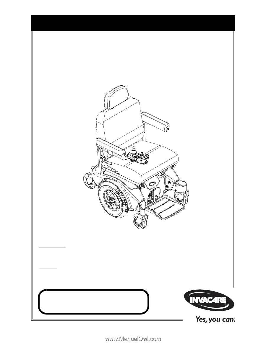
Owner’s Operator and Maintenance Manual
DEALER:
This manual MUST be given to
the user of the product.
USER:
BEFORE using this product, read this
manual and save for future reference.
For more information regarding
Invacare products, parts, and services,
please visit www.invacare.com
Pronto
®
M94
™
with SureStep
®