Campbell Scientific AVW200 AVW200-series Vibrating Wire Interfaces
Campbell Scientific AVW200 Manual
 |
View all Campbell Scientific AVW200 manuals
Add to My Manuals
Save this manual to your list of manuals |
Campbell Scientific AVW200 manual content summary:
- Campbell Scientific AVW200 | AVW200-series Vibrating Wire Interfaces - Page 1
INSTRUCTION MANUAL AVW200-series 2-Channel Vibrating Wire Spectrum Analyzer Modules Revision: 1/14 Copyright © 2008-2014 Campbell Scientific, Inc. - Campbell Scientific AVW200 | AVW200-series Vibrating Wire Interfaces - Page 2
- Campbell Scientific AVW200 | AVW200-series Vibrating Wire Interfaces - Page 3
BY CAMPBELL SCIENTIFIC, INC. are warranted by Campbell Scientific, Inc. ("Campbell") to be free from defects in materials and workmanship under normal use and service for twelve (12) months from date of shipment unless otherwise specified in the corresponding Campbell pricelist or product manual - Campbell Scientific AVW200 | AVW200-series Vibrating Wire Interfaces - Page 4
. Please visit www.campbellsci.com to determine which Campbell Scientific company serves your country. To obtain a Returned Materials Authorization (RMA), contact CAMPBELL SCIENTIFIC, INC., phone (435) 227-9000. After an application engineer determines the nature of the problem, an RMA number - Campbell Scientific AVW200 | AVW200-series Vibrating Wire Interfaces - Page 5
Use with Multiplexers 5 2. Measurements 7 2.1 Vibrating Wire 7 2.2 Temperature 10 3. Quick Start Guides 11 3.1 One or Two Sensors (no multiplexers 11 3.1.1 Direct RS-232 Connection 11 3.1.2 Wireless Connection 12 3.2 Multiplexers Controlled by AVW200 14 3.2.1 Direct RS-232 Connection 14 - Campbell Scientific AVW200 | AVW200-series Vibrating Wire Interfaces - Page 6
Mode 48 7.4 AVW200( ) Instruction Running in the Sequential Mode 49 7.4.1 AVW200 Controlling Two Multiplexers in Sequential Mode ... 50 7.4.2 Datalogger Controlling Two Multiplexers in Sequential Mode . 50 7.5 SDI-12 Example 51 8. Troubleshooting Communication Problems ..........54 8.1 Unable - Campbell Scientific AVW200 | AVW200-series Vibrating Wire Interfaces - Page 7
of AVW200 Interfaces (SDI-12 7 Cutaway of Vibrating Wire Sensor 8 DevConfig plots showing the AVW200 measurement approach.......10 Wiring for Sensor Connections 19 Ground Lug and Power Connectors on the AVW200 20 AVW206 with Whip Antenna 21 Example AM16/32-series to AVW200 Hookup (multiplexers - Campbell Scientific AVW200 | AVW200-series Vibrating Wire Interfaces - Page 8
33 5-8. Options Tab of the Troubleshoot Tool 34 5-9. Graphs for Evaluating Spectral Analysis of a Sensor 35 A-1. Geokon Calibration Report of a Sensor without a Thermistor ........ A-2 B-1. Temperature Measurement Error at Three Temperatures as a Function of Lead Length. Wire is 22 AWG with 16 - Campbell Scientific AVW200 | AVW200-series Vibrating Wire Interfaces - Page 9
Read more! Vibrating Wire Measurements are discussed in detail in Section 2. To simplify programming of the AVW200, engineers implemented firmware to eliminate several parameters that were necessary in programming the older Campbell Scientific interfaces (i.e., AVW1, AVW4, AVW100). i U.S. Patent No - Campbell Scientific AVW200 | AVW200-series Vibrating Wire Interfaces - Page 10
AVW200-series 2-Channel Vibrating Wire Spectrum Analyzer Modules The eliminated parameters are: • Number of steps • Number of cycles • Time of Swept Frequency These parameters are now part of the AVW200 internal operating system and require no user input. The user only needs to input the lower - Campbell Scientific AVW200 | AVW200-series Vibrating Wire Interfaces - Page 11
AVW200-series 2-Channel Vibrating Wire Spectrum Analyzer Modules 1.2 Specifications 1.3 Communication 1.3.1 Datalogger The AVW200 module is designed to work with and complement Campbell Scientific dataloggers, as well as data acquisition products from other manufacturers. 3 - Campbell Scientific AVW200 | AVW200-series Vibrating Wire Interfaces - Page 12
AVW200-series 2-Channel Vibrating Wire Spectrum Analyzer Modules 1.3.1.1 PakBus Protocol/Direct RS-232 Connection When using the PakBus protocol, the AVW200() instruction in CRBasic supports an AVW200 connected to a datalogger via a cable attached to the AVW200's RS-232 port. You can run the - Campbell Scientific AVW200 | AVW200-series Vibrating Wire Interfaces - Page 13
download, and vibrating wire spectrum analysis troubleshooting. To use DevConfig, the AVW200 must be connected to a PC and a power source. DevConfig is bundled in Campbell Scientific's datalogger support software and can also be acquired, at no cost, from Campbell Scientific's website. DevConfig - Campbell Scientific AVW200 | AVW200-series Vibrating Wire Interfaces - Page 14
AVW200-series 2-Channel Vibrating Wire Spectrum Analyzer Modules CR3000 COM1 (C1/C2) CR1000 AVW200 COM2 (C3/C4) COM3 (C5/C6) COM4 (C7/C8) AM16/32B CR3000 CR800, CR850 CR1000 RF401 6 128 - Vibrating Wire Sensors in 4x16 configuration 256 - Vibrating Wire Sensors in 2x32 configuration FIGURE - Campbell Scientific AVW200 | AVW200-series Vibrating Wire Interfaces - Page 15
, CR850 CR1000 CR3000 SDI-12 AVW200-series 2-Channel Vibrating Wire Spectrum Analyzer Modules AVW200 0 AM16/32B 1 2 3 Datalogger MUST Control Multiplexers in SDI-12 Mode FIGURE 1-3. Network of AVW200 Interfaces (SDI-12) 2. Measurements 2.1 Vibrating Wire The spectral approach implemented by the - Campbell Scientific AVW200 | AVW200-series Vibrating Wire Interfaces - Page 16
AVW200-series 2-Channel Vibrating Wire Spectrum Analyzer Modules Diaphragm Vibrating Wire Plucking/ Pickup Coil FIGURE 2-1. Cutaway of Vibrating Wire Sensor There are three user-determined inputs to the AVW200 output of the AVW200 is in Hertz unlike our previous interfaces, which output kHz2 - Campbell Scientific AVW200 | AVW200-series Vibrating Wire Interfaces - Page 17
Campbell Scientific for instructions when this value is given as the Resonant Frequency reading. FIGURE 2-2 (a representative output from the Device Configurator's Troubleshooter) illustrates the AVW200 measurements. The bottom graph shows the raw time series data recorded from a vibrating sensor - Campbell Scientific AVW200 | AVW200-series Vibrating Wire Interfaces - Page 18
AVW200-series 2-Channel Vibrating Wire Spectrum Analyzer Modules Response Amplitude Resonant Frequency Beginning Amplitude Noise Amplitude Noise Frequency Ending Amplitude FIGURE 2-2. DevConfig plots showing the AVW200 measurement approach. Please note that the use of the special FFT algorithm to - Campbell Scientific AVW200 | AVW200-series Vibrating Wire Interfaces - Page 19
AVW200-series 2-Channel Vibrating Wire Spectrum Analyzer Modules Read more! You can find an example program that converts resistance to temperature in Section 7.1.2, and detailed information about the thermistors in Appendix B. 3. Quick Start Guides The AVW200 can be used in many types of systems- - Campbell Scientific AVW200 | AVW200-series Vibrating Wire Interfaces - Page 20
AVW200-series 2-Channel Vibrating Wire Spectrum Analyzer Modules NOTE Check the manufacturer's specification for the sensors frequency and excitation range before picking the begin/end frequencies and excitation voltage. For example, the following AVW200() instructions AVW206 interface transmits - Campbell Scientific AVW200 | AVW200-series Vibrating Wire Interfaces - Page 21
AVW200-series 2-Channel Vibrating Wire Spectrum Analyzer Modules NOTE NOTE 3. Connect an antenna (or antenna cable with the RF401/RF411/RF416 Spread Spectrum Data Radio/Modem manual. 4. Create a CRBasic program that includes an AVW200() instruction for each of the sensors. Check the manufacturer's - Campbell Scientific AVW200 | AVW200-series Vibrating Wire Interfaces - Page 22
AVW200-series 2-Channel Vibrating Wire Spectrum Analyzer Modules 3.2 Multiplexers Controlled by AVW200 3.2.1 Direct RS-232 Connection Sensors Multiplexer AVW200 the vibrating wire sensors to the multiplexer is provided in the AM16/32B manual. 4. Use the 17855 cable to attach the AVW200 to - Campbell Scientific AVW200 | AVW200-series Vibrating Wire Interfaces - Page 23
AVW200-series 2-Channel Vibrating Wire Spectrum Analyzer Modules NOTE Check the manufacturer's specification for the sensors frequency and excitation range before picking the begin/end frequencies and excitation voltage. For example, the following AVW200() instructions can be used to control two - Campbell Scientific AVW200 | AVW200-series Vibrating Wire Interfaces - Page 24
AVW200-series 2-Channel Vibrating Wire Spectrum Analyzer Modules NOTE NOTE At the AVW206 site, do the following steps: 1. Spread Spectrum Data Radio/Modem manual. 4. Create a CRBasic program that includes the AVW200() instruction for each of the multiplexers that the AVW200 will control. Check the - Campbell Scientific AVW200 | AVW200-series Vibrating Wire Interfaces - Page 25
AVW200-series 2-Channel Vibrating Wire Spectrum Analyzer Modules For example, the following AVW200() instructions can be used to control the multiplexers: AVW200(Data1(),ComSDC7,200,200,mux1(1,1),1,1,16,450,3000,2,_60HZ,1,0) AVW200 only option available for non-Campbell Scientific dataloggers. 17 - Campbell Scientific AVW200 | AVW200-series Vibrating Wire Interfaces - Page 26
AVW200-series 2-Channel Vibrating Wire Spectrum Analyzer Modules The following steps are used: 1. Access DevConfig to configure the AVW200 for SDI-12 communications. Go to the Deployment/Measurement tab in DevConfig and enter the SDI-12 Address, multiplexer type, begin frequency, end frequency, and - Campbell Scientific AVW200 | AVW200-series Vibrating Wire Interfaces - Page 27
AVW200-series 2-Channel Vibrating Wire Spectrum Analyzer Modules AVW200 FIGURE 4-1. Wiring for Sensor Connections 4.2 Power and Ground Each AVW200 has a ground lug for connection to earth ground and a green connector for attachment to a power source (see FIGURE 4-2). NOTE Only connect the AVW200 - Campbell Scientific AVW200 | AVW200-series Vibrating Wire Interfaces - Page 28
AVW200-series 2-Channel Vibrating Wire Spectrum Analyzer Modules Connects to earth ground via an 8 AWG wire when not directly connected to a datalogger Connects to a power source via 19246 power cable Indicates AVW200 is connected to a power source FIGURE 4-2. Ground Lug and Power Connectors on the - Campbell Scientific AVW200 | AVW200-series Vibrating Wire Interfaces - Page 29
AVW200-series 2-Channel Vibrating Wire Spectrum Analyzer Modules TABLE 4-2. 17855 or SC110's DTE Cable Wiring Wire Color of 17855 or SC110's see FIGURE 4-3). Ground Lug (connect to earth ground via 8 AWG wire) Lights up when radio is powered; blinks when radio is transmitting Whip Antenna FIGURE - Campbell Scientific AVW200 | AVW200-series Vibrating Wire Interfaces - Page 30
AVW200-series 2-Channel Vibrating Wire Spectrum Analyzer Modules communication between the vibrating wire interface and spread spectrum radio manual. 4.5 Multiplexer Wiring Wire the sensors to the multiplexer according to the multiplexer manual. Other multiplexer wiring depends on whether the AVW200 - Campbell Scientific AVW200 | AVW200-series Vibrating Wire Interfaces - Page 31
AVW200-series 2-Channel Vibrating Wire Spectrum Analyzer Modules FIGURE 4-4. Example AM16/32-series to AVW200 Hookup (multiplexers controlled by AVW200) 4.5.2 Datalogger Controlling the Multiplexer When using SDI-12, the datalogger must control the multiplexer. Use the CABLE4CBL-L cable to connect - Campbell Scientific AVW200 | AVW200-series Vibrating Wire Interfaces - Page 32
AVW200-series 2-Channel Vibrating Wire Spectrum Analyzer Modules AVW200 FIGURE 4-5. AM16/32B to AVW200 Hookup (AM16/32Bs controlled by datalogger and using SDI-12) A CABLE4CBL-L cable is used to connect the multiplexer to the datalogger (see FIGURE 4-6). CABLE SHIELD - Campbell Scientific AVW200 | AVW200-series Vibrating Wire Interfaces - Page 33
AVW200-series 2-Channel Vibrating Wire Spectrum Analyzer Modules 5. Device Configuration (DevConfig) Utility Our Device Configuration (DevConfig) utility is bundled in Campbell Scientific's datalogger support software and can also be acquired, at no cost, from: www.campbellsci.com/downloads. - Campbell Scientific AVW200 | AVW200-series Vibrating Wire Interfaces - Page 34
AVW200-series 2-Channel Vibrating Wire Spectrum Analyzer Modules FIGURE 5-1. Opening Page in DevConfig 5. Select the Serial Port matching the COM port on your computer in which the AVW200 is connected. 6. Press the Connect button. The device may take up to 60 seconds to respond to DevConfig, and for - Campbell Scientific AVW200 | AVW200-series Vibrating Wire Interfaces - Page 35
AVW200-series 2-Channel Vibrating Wire Spectrum Analyzer Modules FIGURE 5-2. Deployment Communications Editor in DevConfig NOTE Certain AVW206 settings must match the RF401 settings for communications between the interface and radio to be successful. Description of the Communication Settings - Campbell Scientific AVW200 | AVW200-series Vibrating Wire Interfaces - Page 36
AVW200-series 2-Channel Vibrating Wire Spectrum Analyzer Modules Net Address-enter the radio network address that matches all of the RF401 radios and other AVW206 in the network. select Low for the Retry Level.) Once the settings have been defined, press Apply to save the changes to the AVW200. 28 - Campbell Scientific AVW200 | AVW200-series Vibrating Wire Interfaces - Page 37
AVW200-series 2-Channel Vibrating Wire Spectrum Analyzer Modules 5.2.2 Measurement The Deployment/Measurement Tab is used Frequency, End Frequency, and excitation parameters are entered in the AVW200() CRBasic instruction (see Section 6, Programming). Description of the Measurement Settings follows: - Campbell Scientific AVW200 | AVW200-series Vibrating Wire Interfaces - Page 38
AVW200-series 2-Channel Vibrating Wire Spectrum Analyzer Modules Multiplexer Type-choose the appropriate multiplexer. The default Once the settings have been defined, press Apply to save the changes to the AVW200. 5.3 Data Monitor The Data Monitor tab in DevConfig can display either the Public - Campbell Scientific AVW200 | AVW200-series Vibrating Wire Interfaces - Page 39
AVW200-series 2-Channel Vibrating Wire Spectrum Analyzer Modules Read more! Appendix D lists the fields in the public table and provides a brief description of each. The status table contains system operating status information accessible ( - Campbell Scientific AVW200 | AVW200-series Vibrating Wire Interfaces - Page 40
AVW200-series 2-Channel Vibrating Wire Spectrum Analyzer Modules 5.4 Send OS For most applications, Campbell Scientific does not anticipate that it will be necessary to download a new operating system to the AVW200. However, if a new operating system (OS) is required, in order to send a new OS to - Campbell Scientific AVW200 | AVW200-series Vibrating Wire Interfaces - Page 41
AVW200-series 2-Channel Vibrating Wire Spectrum Analyzer Modules 5.5 Troubleshoot The Troubleshoot tool in DevConfig can be used to evaluate the frequency spectrum of a sensor and to determine the most appropriate beginning and ending frequencies for a sensor. To access the Troubleshoot Tool, use - Campbell Scientific AVW200 | AVW200-series Vibrating Wire Interfaces - Page 42
AVW200-series 2-Channel Vibrating Wire Spectrum Analyzer Modules FIGURE 5-8. Options Tab of the Troubleshoot Tool 4. Select the AVW200 channel either 1 or 2 and the multiplexer channel that the sensor is attached. If not using a multiplexer, then set the multiplexer channel to one. 5. Once the - Campbell Scientific AVW200 | AVW200-series Vibrating Wire Interfaces - Page 43
AVW200-series 2-Channel Vibrating Wire Spectrum Analyzer Modules Response Amplitude Resonant Frequency Beginning Amplitude Noise Amplitude Noise Frequency Ending Amplitude FIGURE 5-9. Graphs for Evaluating Spectral Analysis of a Sensor NOTE Check the manufacturer's specification - Campbell Scientific AVW200 | AVW200-series Vibrating Wire Interfaces - Page 44
AVW200-series 2-Channel Vibrating Wire Spectrum Analyzer Modules 5.6 Settings Editor The Settings Editor in DevConfig can also be used to enter the Deployment parameters (see FIGURE 5-2). Refer to Section 5.2, Deployment Tab, and Section 5.3, - Campbell Scientific AVW200 | AVW200-series Vibrating Wire Interfaces - Page 45
AVW200-series 2-Channel Vibrating Wire Spectrum Analyzer Modules CAUTION When using the "Mcmm" terminal command, the AVW200 instruction shows up in the editor. The AVW200 instruction is used to read measurements from one or more vibrating wire sensors when the sensors are connected to the AVW200 - Campbell Scientific AVW200 | AVW200-series Vibrating Wire Interfaces - Page 46
AVW200-series 2-Channel Vibrating Wire Spectrum Analyzer Modules instructions are ran in a sequential mode, a different result variable should be specified for each AVW200 (see 6.1.2). The result codes are as follows: Code 0 >1 -3 Description Communication successful. Values have been written to - Campbell Scientific AVW200 | AVW200-series Vibrating Wire Interfaces - Page 47
AVW200-series 2-Channel Vibrating Wire Spectrum Analyzer Modules using the CRBasic AVW200 instruction, the signal Troubleshoot" tab in DevConfig (Section 5.5, Troubleshoot) to examine signal strength amplitude values. The AVWChan is the channel on the AVW200 where the sensor or multiplexer is wired - Campbell Scientific AVW200 | AVW200-series Vibrating Wire Interfaces - Page 48
AVW200-series 2-Channel Vibrating Wire Spectrum Analyzer Modules BeginFreq The BeginFreq parameter is the starting frequency to use for the vibrating wire measurement. The minimum value that can be entered is 100. Refer to the specifications of the vibrating wire the AVW200 CRBasic instruction is - Campbell Scientific AVW200 | AVW200-series Vibrating Wire Interfaces - Page 49
AVW200-series 2-Channel Vibrating Wire Spectrum Analyzer Modules 6.1.1 Pipeline Mode When the CRBasic program first starts running, the information specified in the AVW200( ) instruction is sent to the attached AVW200 interface module via the communication port and PakBus address specified in the - Campbell Scientific AVW200 | AVW200-series Vibrating Wire Interfaces - Page 50
AVW200-series 2-Channel Vibrating Wire Spectrum Analyzer Modules detected. Therefore, the result variable for the first instruction would be zero (indicating successful communication) and the result variable for the second instruction would increment (indicating a failed communication). In the - Campbell Scientific AVW200 | AVW200-series Vibrating Wire Interfaces - Page 51
AVW200-series 2-Channel Vibrating Wire Spectrum Analyzer Modules SDIPort the SDI12 sensor that will be affected by this instruction. Valid addressses are 0 through 9, A through (Measures AVW200 Channel 1; either this command or the following command is used for non-Campbell Scientific dataloggers) - Campbell Scientific AVW200 | AVW200-series Vibrating Wire Interfaces - Page 52
AVW200-series 2-Channel Vibrating Wire Spectrum Analyzer Modules If a check summed command fails, a NAN will be returned and the command will be retried. Mult, Offset The Mult and Offset parameters are each a constant, - Campbell Scientific AVW200 | AVW200-series Vibrating Wire Interfaces - Page 53
AVW200-series 2-Channel Vibrating Wire Spectrum Analyzer Modules 7. Example Programs This section includes several program (6,Dst(2,1),IEEE4) EndTable 'stores data from both sensors into a table named AVW200 'The CardOut instruction is used to create a new DataTable that will be saved on a - Campbell Scientific AVW200 | AVW200-series Vibrating Wire Interfaces - Page 54
AVW200-series 2-Channel Vibrating Wire Spectrum Analyzer Modules CallTable avw200 CallTable avwcard NextScan EndProg 7.1.2 Wireless/One BeginProg Scan (10,Sec,0,0) PanelTemp (PTemp,250) Battery (Batt_volt) AVW200(VWResults,ComSDC7,0,15,VWvalues(1),1,1,1,1000,2500,2,_60Hz,1,0) Digits = (Freq/1000)^2 - Campbell Scientific AVW200 | AVW200-series Vibrating Wire Interfaces - Page 55
AVW200-series 2-Channel Vibrating Wire Spectrum Analyzer Modules 'Calculate displacement (inches) from Digits and calibration polynomial PSI=2.49866e-10*Digits^2 + 8.716e-5*Digits + -.2 NextScan EndProg 7.2 AVW200() Instruction Controlling Two Multiplexers TABLE 7-2 shows wiring used for this - Campbell Scientific AVW200 | AVW200-series Vibrating Wire Interfaces - Page 56
AVW200-series 2-Channel Vibrating Wire Spectrum Analyzer Modules 7.3 AVW200( ) Instruction Running in the Pipeline Mode The following program is an example of how to run the AVW200 with a CR1000 using multiple AVW200( ) instructions in the pipeline mode of operation. When this CRBasic program first - Campbell Scientific AVW200 | AVW200-series Vibrating Wire Interfaces - Page 57
AVW200-series 2-Channel Vibrating Wire Spectrum Analyzer Modules ' Example Program running in the PipeLine mode ' The clock and reset lines of both muxes are connected to the clk and rst 'lines of the AVW200. PipeLineMode Public PTemp, batt_volt Public Result, AVWDst(32,6) Const Chan1 = 1 Const - Campbell Scientific AVW200 | AVW200-series Vibrating Wire Interfaces - Page 58
AVW200-series 2-Channel Vibrating Wire Spectrum Analyzer Modules TABLE 7-4 shows the wiring used for both Sequential Mode examples. TABLE 7-4. Wiring for Sequential Mode Examples Datalogger Port for Cable Attachment COM1 (control port pairs C1/C2) Cable Needed to AVW200 Port or connect to - Campbell Scientific AVW200 | AVW200-series Vibrating Wire Interfaces - Page 59
AVW200-series 2-Channel Vibrating Wire Spectrum Analyzer Modules Const Chan1 = 1 Const Chan2 = 2 Const MuxChan = 1 Const Reps = 1 Const BFreq = 450 Const EFreq = 6000 Const Xvolt = 2 ' AVW200 channel 1 ' AVW200 channel 2 ' Starting Mux Channel ' Number of Reps ' Begin Frequency ' End Frequency ' - Campbell Scientific AVW200 | AVW200-series Vibrating Wire Interfaces - Page 60
AVW200-series 2-Channel Vibrating Wire Spectrum Analyzer Modules very next measurement will TABLE 7-5. SDI-12 Command Codes SDI12 Measurement Command aM! (Measures both AVW200 Chan1 & Chan2) aM1! (Measures AVW200 Chan1) aM2! (Measures AVW200 Chan2) aV! aXVWbbbb,eeee,v! where: bbbb = Begin Freq (100 - Campbell Scientific AVW200 | AVW200-series Vibrating Wire Interfaces - Page 61
AVW200-series 2-Channel Vibrating Wire Spectrum Analyzer Modules ' Example Program running SDI12 commands with the , Mux On, both mux's share this reset port ' delay before clocking Measure 16 vibrating wire sensor on AVW200 channel 1 For I=1 To 16 ' Advance Mux #1 (clock line connected to C4; - Campbell Scientific AVW200 | AVW200-series Vibrating Wire Interfaces - Page 62
AVW200-series 2-Channel Vibrating Wire Spectrum Analyzer Modules 8. Troubleshooting Communication Problems 8.1 Unable to Communicate with DevConfig or Terminal Emulator If you are unable to communicate with DevConfig or the Terminal Emulator, verify that: (1) The AVW200 is powered. The red LED at - Campbell Scientific AVW200 | AVW200-series Vibrating Wire Interfaces - Page 63
AVW200-series 2-Channel Vibrating Wire Spectrum Analyzer Modules Power supply must be able to sustain at least (de-sense) the AVW206 receiver resulting in failed packets and LoggerNet retries. This problem could also occur if you located an AVW206 at a site containing commercial transmitters or - Campbell Scientific AVW200 | AVW200-series Vibrating Wire Interfaces - Page 64
AVW200-series 2-Channel Vibrating Wire Spectrum Analyzer Modules b. Change to a higher gain antenna c. Change polarization (element orientation) of all antennas in your network (yagi or collinear) from vertical to horizontal or vice versa. 9. - Campbell Scientific AVW200 | AVW200-series Vibrating Wire Interfaces - Page 65
Appendix A. Conversion from Hertz The calibration report provided with each vibrating wire sensor contains the information required to convert Hertz, the frequency value output by the AVW200, to the appropriate units (e.g., displacement pressure). These steps convert Hertz to the appropriate unit - Campbell Scientific AVW200 | AVW200-series Vibrating Wire Interfaces - Page 66
Appendix A. Conversion from Hertz FIGURE A-1. Geokon Calibration Report of a Sensor without a Thermistor A-2 - Campbell Scientific AVW200 | AVW200-series Vibrating Wire Interfaces - Page 67
Appendix B. Thermistor Information B.1 Converting Resistance to Temperature The AVW200 outputs a resistance value for sensors that contain a thermistor. Temperature a function of the following factors: 1. Thermistor's interchangeability 2. Resistance of the wire 3. Steinhart-Hart Equation error B-1 - Campbell Scientific AVW200 | AVW200-series Vibrating Wire Interfaces - Page 68
the bridge resistors Errors three through six can probably be ignored. The wire resistance is primarily an offset error and its affect can be removed by through FIGURE B-4 show how wire resistance affects the temperature measurement for a Geokon 4500 Vibrating Wire Piezometer. FIGURE B-1. Temperature - Campbell Scientific AVW200 | AVW200-series Vibrating Wire Interfaces - Page 69
Appendix B. Thermistor Information FIGURE B-2. Temperature Measurement Error on a 1000 foot Lead. Wire is 22 AWG with 16 ohms per 1000 feet. FIGURE B-3. Temperature Measurement Error on a 3000 foot Lead. Wire is 22 AWG with 16 ohms per 1000 feet. B-3 - Campbell Scientific AVW200 | AVW200-series Vibrating Wire Interfaces - Page 70
Appendix B. Thermistor Information FIGURE B-4. Temperature Measurement Error on a 5000 foot Lead. Wire is 22 AWG with 16 ohms per 1000 feet. B-4 - Campbell Scientific AVW200 | AVW200-series Vibrating Wire Interfaces - Page 71
field strengths in excess of FCC rules, interfere with licensed services, and result in FCC sanctions against user. NOTE An FCC 900 MHz, INDOOR OMNI ½ WAVE DIPOLE, 10 ft. cable with SMA connector to fit RF401 Series, window or wall mounted by sticky back, 4 inches wide. 6 dBd ANTENNA, 900 MHz - Campbell Scientific AVW200 | AVW200-series Vibrating Wire Interfaces - Page 72
this happen it could pose a serious interference problem to authorized radio communications such as emergency, broadcast comply with the FCC RF exposure requirements, the AVW206 series may be used only with approved antennas that have of this manual for important FCC information. ITEM # 14310 900 MHZ OMNI ¼ - Campbell Scientific AVW200 | AVW200-series Vibrating Wire Interfaces - Page 73
Appendix C. Antennas, Antenna Cables, and Surge Protectors for the AVW206, AVW211, and AVW216 ITEM # 14204 900 MHZ OMNI ½ WAVE WHIP 0 dBd ITEM # 14201 900 MHZ YAGI 9 dBd w/MOUNTS ITEM #14205 900 MHz YAGI 6 dBd w/MOUNTS ITEM # 14221 900 MHZ OMNI COLLINEAR 3 dBd w/MOUNTS C-3 - Campbell Scientific AVW200 | AVW200-series Vibrating Wire Interfaces - Page 74
Appendix C. Antennas, Antenna Cables, and Surge Protectors for the AVW206, AVW211, and AVW216 ITEM #15970 900 MHZ Indoor OMNI 1 dBd Window/Wall Mounted ITEM #16005 2.4 GHz OMNI HALF WAVE WHIP 0 dBd ITEM #16755 2.4 GHz ENCLOSED YAGI, 13 dBd w/MOUNTS FIGURE C-1. Some FCC Approved Antennas C-4 - Campbell Scientific AVW200 | AVW200-series Vibrating Wire Interfaces - Page 75
Appendix C. Antennas, Antenna Cables, and Surge Protectors for the AVW206, AVW211, and AVW216 FIGURE C-2. Example COAX RPSMA-L Cable for Yagi or Omni Colinear FIGURE C-3. Antenna Surge Protector C.2 Antenna Cables The 14201, 14203, 14205, 14221, and 16755 antennas require an antenna cable; either - Campbell Scientific AVW200 | AVW200-series Vibrating Wire Interfaces - Page 76
signal loss • When the interface will be used in an environment Protector Kit for the RF401 series radios includes the following: Ground wire lead • Screw and grommet to secure ground wire and polyphaser AVW216 not expressly approved by Campbell Scientific, Inc. could void with the instructions, may - Campbell Scientific AVW200 | AVW200-series Vibrating Wire Interfaces - Page 77
Appendix C. Antennas, Antenna Cables, and Surge Protectors for the AVW206, AVW211, and AVW216 This device complies with part 15 of the FCC Rules. Operation is subject to the following two conditions: 1) This device may not cause harmful interference, and 2) This device must accept any interference - Campbell Scientific AVW200 | AVW200-series Vibrating Wire Interfaces - Page 78
Appendix C. Antennas, Antenna Cables, and Surge Protectors for the AVW206, AVW211, and AVW216 C-8 - Campbell Scientific AVW200 | AVW200-series Vibrating Wire Interfaces - Page 79
the AVW200 displays the current sensor measurement values as well as the current settings (see TABLE D-1). When the DeviceConfig runs the troubleshooter, it Stamp Time the record was recorded Control Parameters for AVW200 Instruction Communications Result Result of the last measurement NumReps - Campbell Scientific AVW200 | AVW200-series Vibrating Wire Interfaces - Page 80
measurement SDIEFreq End frequency used for SDI-12 measurement SDIExVolt Excitation voltage used for SDI-12 measurement Value of Last Instruction That's Running Ch1Freq Frequency value measured on channel 1 Ch1Amp Amplitude value measured on channel 1 Ch1SNR Signal to noise ratio measured - Campbell Scientific AVW200 | AVW200-series Vibrating Wire Interfaces - Page 81
Public Table Control Parameters When Troubleshooter is Running TimeSeries(1) Writing this variable will force a Vibrating Wire measurement and create the TimeSeries.bin and spectrum.bin files. Example: 101 = measures AVW200 chan1 and Mux chan1 102 = measures AVW200 chan1 and Mux chan2 ..... 201 - Campbell Scientific AVW200 | AVW200-series Vibrating Wire Interfaces - Page 82
Appendix D. The Public Table D.1 Forced Measurement Program SequentialMode Public UsrForcedMsmnt Public SVResult(2), GVResult(2), TimeSeries(11) Dim TS_done BeginProg TimeSeries(1) = 101 'Measure command with XYY as described below. 'X is the AVW channel, 1 or 2, and YY is the multiplexer - Campbell Scientific AVW200 | AVW200-series Vibrating Wire Interfaces - Page 83
information can be retrieved by the datalogger by using the CRBasic GetVariable instruction. Following is an example of retrieving the BattVoltage status of the AVW200 using the CRBasic GetVariables instruction: Public RC,AVW_BV GetVariables(RC,ComSDC7,200,200,0000,0,"Status","BattVoltage",AVW_BV - Campbell Scientific AVW200 | AVW200-series Vibrating Wire Interfaces - Page 84
When Rf_ForceOn is set to 1 the radio is always on Yes ignoring the duty cycle setting. Identifies the radio protocol that will be used. The AVW200 is always fixed at 2 (PakBus Aware mode) Yes (changing this parameter to a value of 1 will mess up the RF communication). All other values will revert - Campbell Scientific AVW200 | AVW200-series Vibrating Wire Interfaces - Page 85
the current scan. When making the vibration wire measurement it is normal for the modules have 128 Kbytes of SRAM and newer modules have 512 Kbytes of SRAM. If the SRAMMemSize = 512 K, then the AVW200 instruction GetFile(). A post-processing program in DevConfig under device type AVW200 Series - Campbell Scientific AVW200 | AVW200-series Vibrating Wire Interfaces - Page 86
Appendix E. Status Table E-4 - Campbell Scientific AVW200 | AVW200-series Vibrating Wire Interfaces - Page 87
wire vibration is physically changed by the package movement). The AVW200 computes a signal-to-noise diagnostic by dividing the response amplitude by the noise amplitude. The "Time Series of narrowing can be of value for troubleshooting and solving problems with errant sensors, or improving the - Campbell Scientific AVW200 | AVW200-series Vibrating Wire Interfaces - Page 88
Appendix F. Time Series and Spectrum Graph Information FIGURE F-1. Good Sensor with a Narrower Range (200 to 2200 Hz) FIGURE F-2. Good Sensor with a Wider Range (200 to 6500 Hz) F-2 - Campbell Scientific AVW200 | AVW200-series Vibrating Wire Interfaces - Page 89
sensor is measured with the drill a few inches away, the harmonics of the 60 Hz are a lot less and are not more dominate than the wire's natural frequency. Sensors with a frequency range that are below 450 Hz should work fine even in the presence of a 50 or 60 Hz noise source - Campbell Scientific AVW200 | AVW200-series Vibrating Wire Interfaces - Page 90
Appendix F. Time Series and Spectrum Graph Information FIGURE F-4. Good Sensor with Noise (450 to 6500 Hz) NOTE Check the manufactures specification for the sensors frequency and excitation range before picking the begin/end frequencies and excitation voltage. F-4 - Campbell Scientific AVW200 | AVW200-series Vibrating Wire Interfaces - Page 91
Appendix G. CR10X Programming Example Although this example is for the CR10X, the CR23X is programmed similarly. ;{CR10X} ; ; ; *Table 1 Program 01: 900 Execution Interval (seconds) 1: Do (P86) 1: 42 Set Port 2 High 2: Beginning of Loop (P87) 1: 0000 Delay 2: 16 Loop Count 3: Do (P86) - Campbell Scientific AVW200 | AVW200-series Vibrating Wire Interfaces - Page 92
Appendix G. CR10X Programming Example 10: Z=X (P31) 1: 95 2: 65 X Loc [ DcayRatio ] -- Z Loc [ Decay_1 ] ;Write Decay Ratio to inlocs 65-80 11: Z=X (P31) 1: 96 2: 81 X Loc [ Thrmister ] -- Z Loc [ Therm_1 ] ;Write Thermister resistance to inlocs 81-96 12: Z=X*F (P37) 1: 76 2: .001 3: 76 -- X - Campbell Scientific AVW200 | AVW200-series Vibrating Wire Interfaces - Page 93
Multiplexer H.1.1 Direct RS-232 Connection 'This is an example of a program used by a CR1000 and AVW200 to control two AM16/32B multiplexers. 'Sixteen Geokon 4450 VW displacement sensors are attached to each multiplexer and each sensor 'provides a frequency, which is converted - Campbell Scientific AVW200 | AVW200-series Vibrating Wire Interfaces - Page 94
Appendix H. Additional Programming Examples Sample (16,Displacement2(),FP2) Sample (16,VWfreq2(),FP2) Sample (16,Temp2(),FP2) Sample (16,Amp2(),FP2) Sample (16,Sig2Noise2(),FP2) Sample (16,FreqOfNoise2(),FP2) Sample (16,DecayRatio2(),FP2) EndTable BeginProg SerialOpen (COMRS232,38400,0,0,10000) - Campbell Scientific AVW200 | AVW200-series Vibrating Wire Interfaces - Page 95
variables For i = 1 To 16 SplitStr (PolyCoef2(3*i-2),CoefString2(i),",",3,5) Next i Scan (2,Min,0,0) PanelTemp (PTemp,250) Battery (Batt_volt) AVW200(VWResults(1),ComRS232,0,15,Mux1(1,1),1,1,16,1000,2500,2,_60Hz,1,0) For i = 1 To 16 Amp1(i) = Mux1(i,2) Therm1(i) = Mux1(i,6) VWFreq1 - Campbell Scientific AVW200 | AVW200-series Vibrating Wire Interfaces - Page 96
Appendix H. Additional Programming Examples H.1.2 Wireless/Sensors with Different Frequencies ' 'This is an example of a program used by a CR1000 and AVW206 to control two 'AM16/32B multiplexers. Sixteen Geokon 4450 VW displacement sensors are 'attached to each multiplexer and each sensor provides - Campbell Scientific AVW200 | AVW200-series Vibrating Wire Interfaces - Page 97
Appendix H. Additional Programming Examples Sample (16,Displacement2(),FP2) Sample (16,VWfreq2(),FP2) Sample (16,Temp2(),FP2) Sample (16,Amp2(),FP2) Sample (16,Sig2Noise2(),FP2) Sample (16,FreqOfNoise2(),FP2) Sample (16,DecayRatio2(),FP2) EndTable BeginProg 'Enter the 3 Polynomial Gage Factors for - Campbell Scientific AVW200 | AVW200-series Vibrating Wire Interfaces - Page 98
polynomial Displacement1(i)=PolyCoef1(3*i-2)*Digits^2 + PolyCoef1(3*i-1)*Digits + PolyCoef2(3*i) Next i 'Sensors 1-8 are excited over the freq range of 1000 - 2500 AVW200(VWResults(2),ComME,0,20,Mux2(1,1),2,1,8,1000,2500,2,_60Hz,1,0) 'Sensors 9-16 are excited over the freq range of 450 - 6500 - Campbell Scientific AVW200 | AVW200-series Vibrating Wire Interfaces - Page 99
attached to four AM16/32 multiplexers. The four multiplexers are controlled directly 'by the data logger, not through the AVW200 as in other examples contained in this 'manual. Displacement is calculated from the measured frequencies by applying the 'Polynomial Gage Factors contained in each sensors - Campbell Scientific AVW200 | AVW200-series Vibrating Wire Interfaces - Page 100
Appendix H. Additional Programming Examples Sample (16,Sig2Noise2(),FP2) Sample (16,FreqOfNoise2(),FP2) Sample (16,DecayRatio2(),FP2) Sample (9,Displacement3(),FP2) Sample (9,VWfreq3(),FP2) Sample (9,Temp3(),FP2) Sample (9,Amp3(),FP2) Sample (9,Sig2Noise3(),FP2) Sample (9,FreqOfNoise3(),FP2) Sample - Campbell Scientific AVW200 | AVW200-series Vibrating Wire Interfaces - Page 101
Appendix H. Additional Programming Examples 'Gage Factors for sensors attached to AM16/32 #3 Coef3(1) = 2.73949e-10: Coef3(2) = 8.726e-5: Coef3(3) = -0.20799 Coef3(4) = 3.17163e-10: Coef3(5) = 8.741e-5: Coef3(6) = -0.19108 Coef3(7) = 2.49866e-10: Coef3(8) = 8.716e-5: Coef3(9) = -0.20003 Coef3(10) = - Campbell Scientific AVW200 | AVW200-series Vibrating Wire Interfaces - Page 102
the following for each of 16 sensors: PulsePort(2,1000) 'Provide pulse to advance to next channel on Mux1 Delay (0,100,mSec) AVW200(VWResults,ComRS232,0,15,Mux(1),1,1,1,2500,3500,2,_60Hz,1,0) 'Make VW measurement VWFreq1(i) = Mux(1) 'Assign vw frequency to the VWFreq1 variable Amp1(i) = Mux - Campbell Scientific AVW200 | AVW200-series Vibrating Wire Interfaces - Page 103
For i = 1 To 32 'Do the following for each of 32 sensors: PulsePort(8,1000) 'Provide pulse to advance to next channel on Mux4 AVW200(VWResults,ComRS232,0,15,Mux(1),1,1,1,2500,3500,2,_60Hz,1,0) 'Make VW measurement VWFreq4(i) = Mux(1) 'Assign vw frequency to the VWFreq2 variable Amp4(i) = Mux - Campbell Scientific AVW200 | AVW200-series Vibrating Wire Interfaces - Page 104
Appendix H. Additional Programming Examples H-12 - Campbell Scientific AVW200 | AVW200-series Vibrating Wire Interfaces - Page 105
with SDI-12 communications. I.1 Required Settings DevConfig is used to configure the settings for the AVW200 interfaces and the MD485 Multidrop modems. A unique address must be assigned to each AVW200 in the network. This address may be entered in the Deployment/Communications or the Setting Editor - Campbell Scientific AVW200 | AVW200-series Vibrating Wire Interfaces - Page 106
Using MD485 Multidrop Modems with AVW200 Interfaces I.2 Connections The point-to-point configuration is the simplest MD485-to-AVW200 network. In this configuration, two MD485s are required (see FIGURE I-2). The point-to-multipoint configuration uses several AVW200s. In this configuration, you need - Campbell Scientific AVW200 | AVW200-series Vibrating Wire Interfaces - Page 107
Appendix I. Using MD485 Multidrop Modems with AVW200 Interfaces Connects to another MD485 via the CABLE2TP Connects to the datalogger's RS-232 port or the AVW200's RS-232 port via a null modem cable Connects to earth ground via an 8 AWG wire FIGURE I-4. MD485 and its connectors. I.2.1 - Campbell Scientific AVW200 | AVW200-series Vibrating Wire Interfaces - Page 108
be used in this configuration but the AVW200 has to control the multiplexers. Refer to Section 4.5.1, AVW200 Controlling the Multiplexer, for information on connecting the multiplexers. I.3 Programming An AVW200() instruction is entered for each AVW200. The ComPort parameter needs to be ComRS232 - Campbell Scientific AVW200 | AVW200-series Vibrating Wire Interfaces - Page 109
Using MD485 Multidrop Modems with AVW200 Interfaces 'CR1000 Series Datalogger 'This program measures 2 sensors on 2 AVW200s PBA1 and PBA5. 'Each AVW200 is connected to a MD485 A=.001403040 Const B=.000237318 const C=.00000009 DataTable (AVW200,1,-1) DataInterval (0,10,Sec,10) Sample (6,Dst(1,1), - Campbell Scientific AVW200 | AVW200-series Vibrating Wire Interfaces - Page 110
Appendix I. Using MD485 Multidrop Modems with AVW200 Interfaces I-6 - Campbell Scientific AVW200 | AVW200-series Vibrating Wire Interfaces - Page 111
- Campbell Scientific AVW200 | AVW200-series Vibrating Wire Interfaces - Page 112
Santo Domingo, Heredia 40305 COSTA RICA www.campbellsci.cc • [email protected] Campbell Scientific Ltd. (CSL) Campbell Park 80 Hathern Road Shepshed, Loughborough LE12 9GX UNITED KINGDOM www.campbellsci.co.uk • [email protected] Campbell Scientific Ltd. (CSL France) 3 Avenue de la Division
-
 1
1 -
 2
2 -
 3
3 -
 4
4 -
 5
5 -
 6
6 -
 7
7 -
8
-
9
-
10
-
11
-
12
-
13
-
14
-
15
-
16
-
17
-
18
-
19
-
20
-
21
-
22
-
23
-
24
-
25
-
26
-
27
-
28
-
29
-
30
-
31
-
32
-
33
-
34
-
35
-
36
-
37
-
38
-
39
-
40
-
41
-
42
-
43
-
44
-
45
-
46
-
47
-
48
-
49
-
50
-
51
-
52
-
53
-
54
-
55
-
56
-
57
-
58
-
59
-
60
-
61
-
62
-
63
-
64
-
65
-
66
-
67
-
68
-
69
-
70
-
71
-
72
-
73
-
74
-
75
-
76
-
77
-
78
-
79
-
80
-
81
-
82
-
83
-
84
-
85
-
86
-
87
-
88
-
89
-
90
-
91
-
92
-
93
-
94
-
95
-
96
-
97
-
98
-
99
-
100
-
101
-
102
-
103
-
104
-
105
-
106
-
107
-
108
-
109
-
110
-
111
-
112
 |
 |
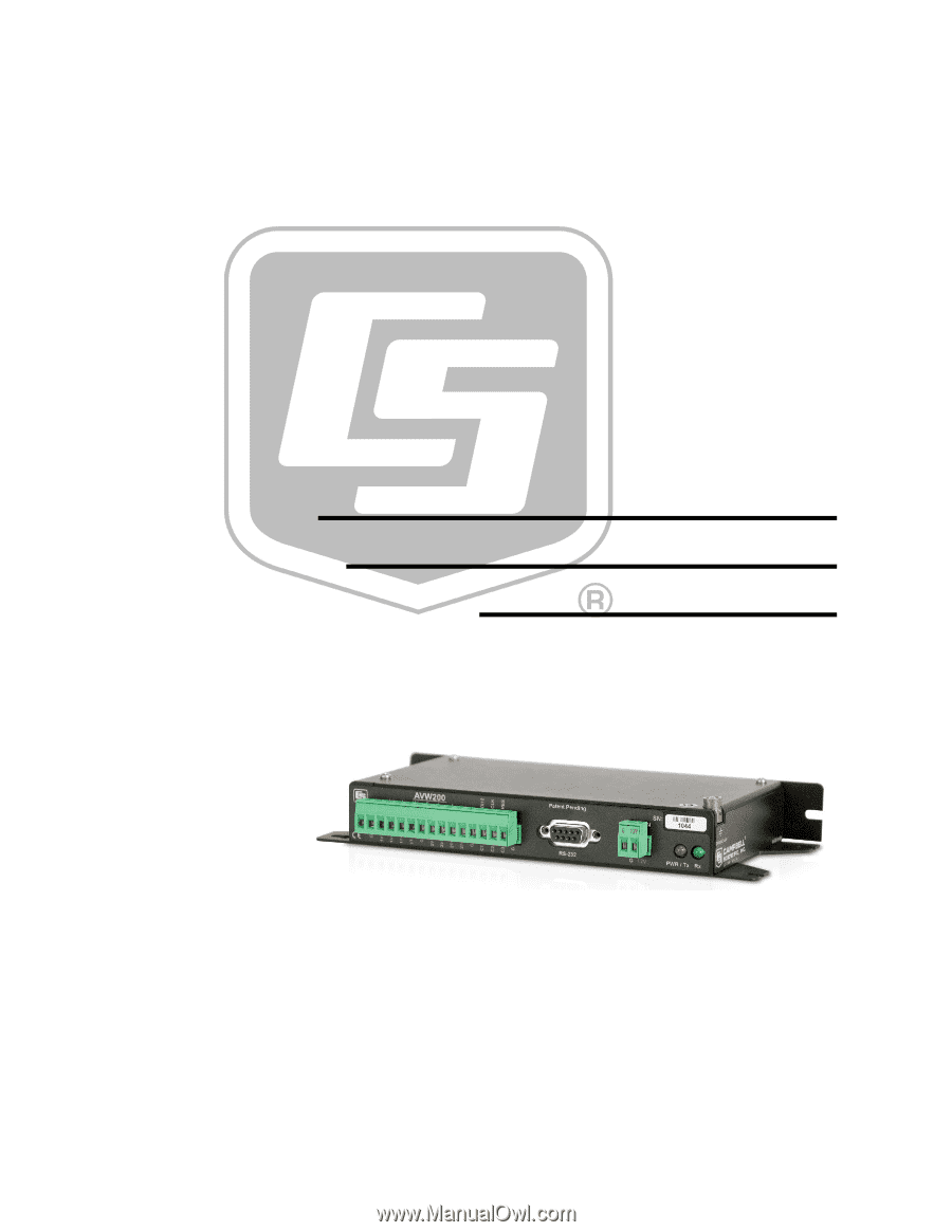
INSTRUCTION MANUAL
AVW200-series 2-Channel
Vibrating Wire Spectrum
Analyzer Modules
Revision: 1/14
Copyright © 2008-2014
Campbell Scientific, Inc.