Yamaha FX900 FX900 Owners Manual Image - Page 8
Connections, Basic, System, Setup - guitar
 |
View all Yamaha FX900 manuals
Add to My Manuals
Save this manual to your list of manuals |
Page 8 highlights
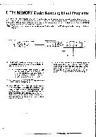
3. Connections: Basic System Setup 000 (DTO®CI T ®CDT ,-FOOT ,-FOOT VOL-, REMOTE I 0I OUTPUT INPUT 111,110.1.071 1 O 1 I II O L NO L114101 MIT 0 0 '117 0-) YAMAHA .smalmr wocoom ED, ozo.utaoust ,nereorrs MA . = F. rum .. Mr= r,mv.ormaz ..n.roc, srmn..e. ta,,ryzacx. co. O 0 Input IMPEDANCE Switch This switch determines the input impedance of the INPUT R and UMONO jacks, and the front-panel INPUT jack. When directly connecting a guitar or other highimpedance instrument to the FX900, set this switch to the "1M" position. The "10k" setting is appropriate for standard audio equipment and other line-level sources. 73 Input Level -20dB/+4dB Switch This switch allows the input sensitivity of the FX900 to matched to the type of source equipment used. When connecting the FX900 to professional equipment that has +4 dB outputs, set the input level switch to the "+4dB" position. The "-20dB" setting is the best choice for most home-use audio equipment. 0 INPUT R & UMONO Jacks The INPUT R and UMONO jacks allow either stereo or mono signals to be fed to the FX900. Stereo signals should be fed to both jacks, while a mono signal should be fed to the UMONO jack only. Inserting a plug into the UMONO jack only causes the FX900 to function as a 1in/2-out type signal processor. The UMONO jack duplicates the function of the front-panel INPUT jack described in the following section. If plugs are inserted into both the front and rear-panel inputs, the front-panel input jack takes priority. 0 OUTPUT R and OUTPUT L Jacks These are the main stereo outputs from the FX900. We recommend using both outputs and connecting them to the corresponding right and left channels of a stereo sound system, since the full impact of many of the FX900 effects can only be appreciated in stereo. If, however, only a mono sound system is available, use either the OUTPUT R or OUTPUT L jack. 0 Output Level -20dB/+4dB Switch This switch is used to match the output level of the FX900 to the input sensitivity of the amplifier, mixing console or other device it is feeding. For compatibility with standard line-level inputs the "-20dB" setting should be appropriate, while the "+4dB" setting should be used when the FX900 is connected to professional equipment that has +4dB inputs. 7 ® MIDI IN Connector The MIDI IN connector accepts MIDI signals from an external MIDI device such as a MIDI foot controller, keyboard, etc. The FX900 will accept MIDI PROGRAM CHANGE messages to directly select effect programs, or MIDI CONTROL CHANGE messages via which individual effect parameters may be remotely controlled. JSee oaae 43 for further details' 0 MIDI THRU/OUT Switch Selects either MIDI THRU or MIDI OUT operation for the MIDI THRU/OUT connector, described below. ® MIDI THRU/OUT Connector When the MIDI THRU/OUT switch is set to "THRU," MIDI signals received at the MIDI IN connector are retransmitted via this connector in real time, allowing other MIDI devices to be "chained" to the FX900. When the MIDI THRU/OUT switch is set to "OUT," MIDI data corresponding to operation of the FX900 is transmitted via this connector. 'See page 49 for further details' 0 REMOTE Connector This connector accepts the optional FC900 remote foot controller unit, allowing convenient foot control of effect group switching, program selection, bypass switching, and other functions. ® FOOT VOL 1 and 2 Jacks Optional Yamaha FC7 Foot Controllers connected to the FOOT VOL 1 and 2 jacks can be used to control specified effect parameters in real time. 'See page 45 for further details' 0 MEMORY INC/DEC Jack An optional Yamaha FC4 or FC5 Footswitch may be connected here for convenient foot-controlled selection of effect programs. The range of effect programs that can be selected is determined by the UTILITY mode Footswitch Memory Recall Range Edit function (page 48). "See one 48 for further details' BYPASS Jack An optional Yamaha FC4 or FC5 Footswitch connected here performs exactly the same function as the frontpanel [BYPASS] key. Press the footswitch once to activate the bypass mode, and again to turn bypass off.
-
 1
1 -
2
-
 3
3 -
 4
4 -
 5
5 -
 6
6 -
 7
7 -
 8
8 -
 9
9 -
 10
10 -
 11
11 -
 12
12 -
 13
13 -
14
-
15
-
16
-
17
-
18
-
19
-
20
-
21
-
22
-
23
-
24
-
25
-
26
-
27
-
28
-
29
-
30
-
31
-
32
-
33
-
34
-
35
-
36
-
37
-
38
-
39
-
40
-
41
-
42
-
43
-
44
-
45
-
46
-
47
-
48
-
49
-
50
-
51
-
52
-
53
-
54
-
55
-
56
-
57
-
58
-
59
-
60
-
61
-
62
-
63
-
64
-
65
-
66
-
67
-
68
-
69
-
70
-
71
-
72
-
73
-
74
-
75
-
76
-
77
-
78
-
79
-
80
-
81
-
82
-
83
-
84
-
85
-
86
-
87
-
88
-
89
-
90
-
91
-
92
-
93
-
94
-
95
-
96
-
97
-
98
-
99
-
100
-
101
-
102
-
103
-
104
-
105
-
106
-
107
-
108
-
109
-
110
-
111
-
112
-
113
-
114
-
115
-
116
-
117
-
118
-
119
-
120
-
121
-
122
-
123
-
124
-
125
-
126
-
127
-
128
-
129
-
130
-
131
-
132
-
133
-
134
-
135
-
136
-
137
-
138
-
139
-
140
-
141
-
142
-
143
-
144
-
145
-
146
-
147
-
148
-
149
-
150
-
151
-
152
-
153
-
154
-
155
-
156
-
157
-
158
-
159
-
160
-
161
-
162
-
163
-
164
-
165
-
166
-
167
-
168
-
169
-
170
-
171
-
172
-
173
-
174
-
175
-
176
 |
 |
