LiftMaster CAPXLV Installation Manual - English French Spanish - Page 19
Gate Access (Wireless), Outputs, Test Relay
 |
View all LiftMaster CAPXLV manuals
Add to My Manuals
Save this manual to your list of manuals |
Page 19 highlights
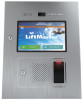
INTRODUCTION PRE-INSTALL INSTALL NETWORK ACCESS CONTROL Gate Access (Wireless) The CAPXL / CAPXLV can communicate wirelessly to LiftMaster® UL325 gate operators to send open commands, monitor gate position, and send email notifications if an error occurs in the operator (email notifications are configured in myQ® Business™). Up to 8 gate operators can be paired with the CAPXL / CAPXLV - one for each primary and auxiliary relay. If using dual gates, program the CAPXL / CAPXLV to the primary operator. 1 Enter Admin Mode Flip dipswitch #1 to the ON position to enter Admin Mode. ON ON 2 Select Outputs and Relay Select the Outputs tab. Then select the desired relay on the left-hand side (1 through 4). 3 Press LEARN button on gate operator Press and release the LEARN button on the primary operator. The green XMITTER LED will light. NOTE: The operator will time out of programming mode after 180 seconds. NOTE: For new installations press the login button without entering information in the Admin Username and Admin Password fields. 4 Press LEARN button on gate operator again Press and release the LEARN button again on the primary operator. The yellow NETWORK LED will light. 5 Select LEARN on display Select the LEARN button on the display and the Learn button will go from blue to red. The gate operator and the CAPXL / CAPXLV will beep once and the NETWORK LED on the gate operator will turn off indicating programming is successful. NOTE: 4 beeps/blinks indicate you are not programming to the primary operator. Reattempt programming from the other operator. 6 Validate Validate functionality by selecting Test Relay on the CAPXL / CAPXLV display. Visit myQBusiness.com for more information on how to set up doors for wireless linking. 19
-
 1
1 -
2
-
3
-
4
-
5
-
6
-
7
-
8
-
9
-
10
-
11
-
12
-
13
-
 14
14 -
 15
15 -
 16
16 -
 17
17 -
 18
18 -
 19
19 -
 20
20 -
 21
21 -
 22
22 -
 23
23 -
 24
24 -
25
-
26
-
27
-
28
-
29
-
30
-
31
-
32
-
33
-
34
-
35
-
36
-
37
-
38
-
39
-
40
-
41
-
42
-
43
-
44
-
45
-
46
-
47
-
48
-
49
-
50
-
51
-
52
-
53
-
54
-
55
-
56
-
57
-
58
-
59
-
60
-
61
-
62
-
63
-
64
-
65
-
66
-
67
-
68
-
69
-
70
-
71
-
72
-
73
-
74
-
75
-
76
-
77
-
78
-
79
-
80
-
81
-
82
-
83
-
84
-
85
-
86
-
87
-
88
-
89
-
90
-
91
-
92
 |
 |
