LiftMaster CAPXLV Installation Manual - English French Spanish
LiftMaster CAPXLV Manual
 |
View all LiftMaster CAPXLV manuals
Add to My Manuals
Save this manual to your list of manuals |
LiftMaster CAPXLV manual content summary:
- LiftMaster CAPXLV | Installation Manual - English French Spanish - Page 1
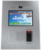
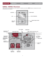
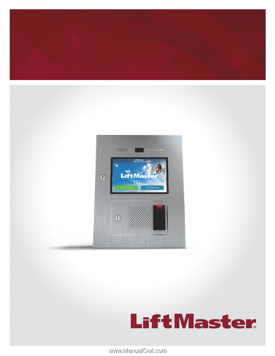
Models CAPXL / CAPXLV myQ® Business™ Connected Access Portal - High Capacity INSTALLATION MANUAL 1 - LiftMaster CAPXLV | Installation Manual - English French Spanish - Page 2
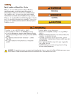
Safety Safety Symbol and Signal Word Review When you see these Safety Symbols and Signal be run in separate conduit. To protect against fire and electrocution: • Disconnect power BEFORE installing or servicing CAPXL / CAPXLV. • NEVER connect a keypad/reader or lock to doors without first consulting - LiftMaster CAPXLV | Installation Manual - English French Spanish - Page 3
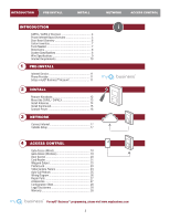
INSTALL Internet Service 11 Phone Provider 11 Setup a myQ® Business™ Account 11 2 INSTALL Remove Knockouts 12 Mount the CAPXL / CAPXLV 13 Install Antennas 14 Install Postal Lock 23 Video Camera Feature 24 Auto-Call Feature 25 Wiring Diagram 26 Repair Parts 27 Accessories 27 Configuration - LiftMaster CAPXLV | Installation Manual - English French Spanish - Page 4
DETECTOR BOARD MOUNTING LOCATION MAIN EARTH GROUND LOCATION Wi-Fi® ANTENNA POWER/INTERNET BOARD ON SENSOR BOARD (CAPXL / CAPXLV) Integrated video camera NOTE: Install only the Liftmaster camera. No other camera will be compatible. Wi-Fi® ANTENNA CONNECTION CONTROL BOARD POSTAL LOCK SWITCH DOOR - LiftMaster CAPXLV | Installation Manual - English French Spanish - Page 5
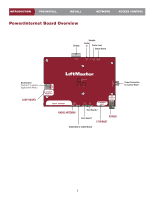
INTRODUCTION PRE-INSTALL INSTALL Power/Internet Board Overview NETWORK ACCESS CONTROL Display Speaker Audio In Postal Lock Sensor Board DISPLAY Dip Switches (Switch #1 is used to ON toggle Admin - LiftMaster CAPXLV | Installation Manual - English French Spanish - Page 6
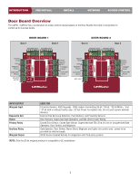
INTRODUCTION PRE-INSTALL INSTALL NETWORK ACCESS CONTROL Door Board Overview The CAPXL / CAPXLV has a combination of access control inputs/outputs on the Door Boards that work in conjunction to third party systems *NOTE: Only the 26-bit weigand protocol is compatible in UL installations. 6 - LiftMaster CAPXLV | Installation Manual - English French Spanish - Page 7
INTRODUCTION PRE-INSTALL Carton Inventory CAPXL/CAPXLV INSTALL NETWORK ACCESS CONTROL PROVIDED (NOT SHOWN) • Installation Manual • Quickstart Guide Power Supply S10K30MOV (Metal Oxide Varistor)(4) Ferrite Core Goose-neck Gasket Radio Antenna (Security+ 2.0®) and Cable Keys (2) 1N4005 - LiftMaster CAPXLV | Installation Manual - English French Spanish - Page 8
Wiegand Inputs (4) 4 Primary and 4 Auxiliary Relay Outputs Accessory Compatibility Network Compatibility Wi-Fi® Compatibility Wi-Fi® Security Wi-Fi® Range Built-in LiftMaster Passport Receiver Wireless Communication to Gate Operator CAPXLV Video Camera Resident Capacity 50,000 / Local Event History - LiftMaster CAPXLV | Installation Manual - English French Spanish - Page 9
installation. DESCRIPTION OF WIRE RUN Power Wire, secondary DC output Local Area Network (LAN) CAT 5 or better Network Cable. CAT 5e and higher is preferred for video. Grounding the Chassis (use grounding lug in CAPXL breaker. This will prevent two problems: • Other equipment cannot introduce - LiftMaster CAPXLV | Installation Manual - English French Spanish - Page 10
router via a wired connection or Wi-Fi. LiftMaster recommends an Internet speed of 25Mbps (Mbits per second) download, 10Mbps upload for best video performance (minimum 10Mbps download speed, 5Mbps upload speed for each CAPXL supporting video camera feeds). NOTE: These upload/download speeds should - LiftMaster CAPXLV | Installation Manual - English French Spanish - Page 11
LiftMaster. Accept the invitation and register or login to your account. 3. Setup the facility, select a subscription plan, add residents, and credentials (refer to the available Help in myQ® Business™). 4. Continue with the installation of the CAPXL / CAPXLV in this manual. 2 Internet Service - LiftMaster CAPXLV | Installation Manual - English French Spanish - Page 12
INTRODUCTION PRE-INSTALL INSTALL NETWORK ACCESS CONTROL 1 Remove Knockouts 1. Turn the key clockwise to unlock the CAPXL / CAPXLV. 2. Open the door and lay the CAPXL / CAPXLV face down on a table with the door hanging off the edge of the table as shown. 3. Identify which knockouts need to be - LiftMaster CAPXLV | Installation Manual - English French Spanish - Page 13
. NOTES: -Ensure the cover can fully open to allow access after the installation is complete. -ADA Compliance: When mounting the CAPXL / CAPXLV at a pedestrian entrance, to meet ADA compliance, mount the top of the CAPXL / CAPXLV screen no higher than 54 inches from the ground. Pedestal Mount - LiftMaster CAPXLV | Installation Manual - English French Spanish - Page 14
8 inches (20 cm) apart. Install the antennas on opposite sides of the CAPXL / CAPXLV. Optional antenna cable kits are available for remote antenna mounting (refer to accessories). Security+ 2.0® Radio Antenna (if applicable) Used with LiftMaster Passport Security+ 2.0® and wireless communication - LiftMaster CAPXLV | Installation Manual - English French Spanish - Page 15
AHJ (Authority Having Jurisdiction) in the municipality where you plan to install the CAPXL / CAPXLV for correct grounding materials and installation procedures. A proper ground is critical to minimizing risk for the CAPXL / CAPXLV from damaging electrical transients. 1. Connect the ground wire (12 - LiftMaster CAPXLV | Installation Manual - English French Spanish - Page 16
The CAPXL / CAPXLV will display the LiftMaster logo while booting up. When boot up is complete, the user interface will appear. 5. Close the CAPXL / outlet until ALL wiring is completed. • Install the transient noise suppression device (MOV) supplied with the CAPXL / CAPXLV for AC powered devices and - LiftMaster CAPXLV | Installation Manual - English French Spanish - Page 17
network. Router/Switch Modem 4. Select Login. Additional compatibility considerations: • When checking signal strength in CAPXL / CAPXLV admin mode, we recommend at least two bars. • If two bars are not available, relocate the router, the antenna or use accessory WFAEXT (Wi-Fi® Antenna Extension - LiftMaster CAPXLV | Installation Manual - English French Spanish - Page 18
gate operator connections.) GATE OPERATOR (connect to Aux Closed Limit switch refer to gate operator manual) EOL (End of Line) Resistor (1k ohm) PRIMARY RELAY GATE OPERATOR LiftMaster® Security+ 2.0® gate operators can be programmed to communicate wirelessly instead of using a wired connection - LiftMaster CAPXLV | Installation Manual - English French Spanish - Page 19
PRE-INSTALL INSTALL NETWORK ACCESS CONTROL Gate Access (Wireless) The CAPXL / CAPXLV can communicate wirelessly to LiftMaster® UL325 of programming mode after 180 seconds. NOTE: For new installations press the login button without entering information in the Admin Username and Admin Password - LiftMaster CAPXLV | Installation Manual - English French Spanish - Page 20
of Line) Resistor (1k ohm) *PRIMARY RELAY DOOR STRIKE For AC Power: Install a Siemens S10K30MOV (Metal Oxide Varistor) (provided) or equivalent Power for Door LOAD LINE NOTE: DO NOT run high voltage power within OR the CAPXL enclosure. ALARM BYPASS COMMON NORMALLY OPEN 20 DOOR 1, 2, 3, - LiftMaster CAPXLV | Installation Manual - English French Spanish - Page 21
the CAPXL / CAPXLV. 3. Install the reader and secure with the screws. 4. Apply silicon around the cable hole. 5. The reader can be wired to any of the 4 Wiegand Inputs on the door control boards. Insulate any unused wires from the CAPXL / CAPXLV to prevent a short. (Refer to instructions provided - LiftMaster CAPXLV | Installation Manual - English French Spanish - Page 22
INTRODUCTION PRE-INSTALL INSTALL NETWORK ACCESS CONTROL LiftMaster LMSC1000 RFID Reader Wiring Diagram Power Transformer LMSC1000 RFID Reader The gray, blue, and brown wires from the RFID Reader are unused. Solid Black Black w/ - LiftMaster CAPXLV | Installation Manual - English French Spanish - Page 23
INTRODUCTION PRE-INSTALL INSTALL NETWORK ACCESS CONTROL Wiegand Output Disconnect power BEFORE making electrical connections. The CAPXL / CAPXLV offers a Wiegand output capable of 26 bit transmission of the following data: • Success Call with access granted by the resident. The CAPXL / CAPXLV - LiftMaster CAPXLV | Installation Manual - English French Spanish - Page 24
supported by CAPXL and myQ® Business™ video features. CAPXLCAM is the only camera evaluated by UL for use with CAPXL. PRIOR TO CAMERA INSTALLATION site to ensure safe operation and resident flow. 3. Login to myQ®Business™ to update the CAPXL to the latest firmware version.Turn off power by - LiftMaster CAPXLV | Installation Manual - English French Spanish - Page 25
INTRODUCTION PRE-INSTALL INSTALL NETWORK ACCESS CONTROL Auto-Call Feature Disconnect power BEFORE input in the CAPXL / CAPXLV main Admin screen (Toggle dip switch #1) Wire Harness LOOP MODE EXIT INTERRUPT SHADOW AUXILIARY SW1 SW2 Not supported Not supported Not supported ON ON LOOP - LiftMaster CAPXLV | Installation Manual - English French Spanish - Page 26
in the wiring diagram and the requirements of your local building codes. The information is for suggested use ONLY. Check your local codes BEFORE installation. orange blue USB Camera red white green black red black red black purple white black white purple blue green yellow orange red POWER - LiftMaster CAPXLV | Installation Manual - English French Spanish - Page 27
-38330 K94-38407 K002B1910 K41-0117-000 Accessories ITEM Back Box and Trim Kit Reader Remote Passport Lite 1-Button Key Chain Remote Passport Lite LiftMaster.com. If you have a specific model of reader or keypad that is not listed on the LiftMaster website, please contact LiftMaster Technical Support - LiftMaster CAPXLV | Installation Manual - English French Spanish - Page 28
Configuration Sheet Record device information and configuration settings below. CAPXL / CAPXLV Name: NOTE: Any user of the system is subject to the terms outlined in the product EULA. Notes: DEVICE CONFIGURATION: DOOR 1 DOOR/GATE NAME: - LiftMaster CAPXLV | Installation Manual - English French Spanish - Page 29
and, if not installed and used in accordance with the instruction manual, may cause harmful is considered the exclusive property of LiftMaster. All information in this document or CAPXL / CAPXLV screen no higher than 54 inches from the ground. NOTE: When installing CAPXLV or retrofitting with a video - LiftMaster CAPXLV | Installation Manual - English French Spanish - Page 30
LiftMaster ("Seller") warrants to the first purchaser of this product, for the structure in which this product is originally installed instructions regarding installation, operation, maintenance and testing. Failure to comply strictly with those instructions REPLACED UNIT, PROBLEMS RELATED TO - LiftMaster CAPXLV | Installation Manual - English French Spanish - Page 31
- LiftMaster CAPXLV | Installation Manual - English French Spanish - Page 32
Modèles de CAPXL / CAPXLV myQ® Business™ Portail d'accès connecté, haute capacité MANUEL D'INSTALLATION 1 - LiftMaster CAPXLV | Installation Manual - English French Spanish - Page 33
sur le CAPXL / CAPXLV. • NE JAMAIS connecter un clavier/lecteur ou une serrure aux portes sans d'abord consulter le code de prévention des incendies applicable. • Il est IMPÉRATIF de consulter les autorités du service local des incendies et d'obtenir leur approbation AVANT d'installer des serrures - LiftMaster CAPXLV | Installation Manual - English French Spanish - Page 34
9 Exigences internet 10 1 PRÉ-INSTALLATION Service internet 11 Fournisseur de service téléphonique 11 Création d'un compte® myQ™ Business 11 2 INSTALLATION Enlever les entrées défonçables 12 Montage du CAPXL / CAPXLV 13 Installation des antennes 14 Installation de la masse 15 Raccordement de - LiftMaster CAPXLV | Installation Manual - English French Spanish - Page 35
LA MISE À LA TERRE PRINCIPALE Antenne Wi-Fi® Carte d'alimentation/Internet ON CARTE DU CAPTEUR Caméra video intégrée (CAPXL / CAPXLV) REMARQUE : Installer uniquement la caméra LiftMaster. Aucune autre caméra ne sera compatible. CONNEXION DE L'ANTENNE Wi-Fi® CARTE LOGIQUE INTERRUPTEUR DE SERRURE - LiftMaster CAPXLV | Installation Manual - English French Spanish - Page 36
INTRODUCCION PRÉINSTALLATION INSTALLATION RÉSEAU CONTRÔLE D'ACCÈS Présentation de la carte d'alimentation/internet Affichage Haut-parleur Entrée audio Verrou postal Carte de capteur DISPLAY Commutateurs DIP ( - LiftMaster CAPXLV | Installation Manual - English French Spanish - Page 37
INTRODUCCION PRÉINSTALLATION INSTALLATION RÉSEAU CONTRÔLE D'ACCÈS Présentation de la carte de la porte Le CAPXL / CAPXLV a une combinaison d'entrées/sorties d'accès sur les cartes de portes qui fonctionnent en conjonction pour commander jusqu'à 4 points d'accès. PORTE 1 PORTE 1 PORTE 2 ENTR - LiftMaster CAPXLV | Installation Manual - English French Spanish - Page 38
RÉSEAU CONTRÔLE D'ACCÈS CONTENU DE LA BOÎTE CAPXL/CAPXLV FOURNI (NON MONTRÉ) • Manuel d'installation • Guide de démarrage rapide Alimentation électrique Joint pour col de cygne Antenne radio (Security+ 2.0®) et câble S10K30MOV (varistance à oxyde métallique)(4) Clés (2) Tore magn - LiftMaster CAPXLV | Installation Manual - English French Spanish - Page 39
/ 8 kV direct / 200 V Mm Plage de températures de service du CAPXL / CAPXLV - 29 °C à 54 °C (-20 °F à 130 LiftMaster Security+ 2.0® Caméra vidéo CAPXLV 1 080 p, angle de visualisation - 135 degrés en diagonale *REMARQUE : Seul le protocole Wiegand de 26 bits est compatible avec les installations - LiftMaster CAPXLV | Installation Manual - English French Spanish - Page 40
REMARQUES : • Pour les distances extérieures dépassant 42,7 m (140 pi), un limiteur de tension primaire conforme à la norme UL497 DOIT être installé au CAPXL / CAPXLV. • Les distances dépassant 100 m (328 pi) peuvent être accommodées par le recours à une quincaillerie supplémentaire (offerte aupr - LiftMaster CAPXLV | Installation Manual - English French Spanish - Page 41
l'information ci-dessous pour garantir la compatibilité. MODÈLE : CAPXL / CAPXLV - Portail d'accès connecté, haute capacité Le CAPXL / CAPXLV peut être connecté à un routeur par le biais d'une connexion câblée ou par le Wi-Fi. LiftMaster recommande une vitesse internet de 25 Mb/s (Mbit par seconde - LiftMaster CAPXLV | Installation Manual - English French Spanish - Page 42
envoyé LiftMaster. Accepter l'invitation et s'inscrire ou ouvrir une session dans le compte. 3. Configurer l'installation et ajouter les résidents et identifiants (consulter la section Aide [Help] dans myQ® Business™). 4. Poursuivre l'installation du CAPXL / CAPXLV dans ce manuel. 2 Service internet - LiftMaster CAPXLV | Installation Manual - English French Spanish - Page 43
enlevant les entrées défonçables, prendre soin d'éviter d'endommager les composants du CAPXL / CAPXLV.. Pour prévenir les dommages au CAPXL / CAPXLV causes par l'eau ou l'humidité : • NE PAS procéder à l'installation sous la pluie. Les composants internes DOIVENT être complètement à l'abri de l'eau - LiftMaster CAPXLV | Installation Manual - English French Spanish - Page 44
:- S'assurer que le couvercle peut s'ouvrir complètement pour permettre l'accès une fois l'installation complétée. -Conformité à l'ADA : Lors du montage du CAPXL / CAPXLV à une entrée pour piétons, monter le dessus de l'écran du CAPXL / CAPXLV à une hauteur ne dépassant pas 137 cm (54 po) du sol - LiftMaster CAPXLV | Installation Manual - English French Spanish - Page 45
une distance minimale entre elles de 20 cm (8 po). Installer les antennes sur les côtés opposés du CAPXL / CAPXLV. Les trousses de câble d'antenne en de barrière LiftMaster 2016 conformes à l'UL325. 1. Enlever l'entrée défonçable de 3/8 po sur le côté ou à l'arrière du CAPXL / CAPXLV. Commande - LiftMaster CAPXLV | Installation Manual - English French Spanish - Page 46
vous comptez installer le CAPXL / CAPXLV pour vous assurer d'utiliser les matériaux adéquats et les bonnes directives d'installation de la masse lectrique ou autres conduites de services publics, contacter les compagnies de localisation de services souterrains AVANT d'entreprendre les travaux - LiftMaster CAPXLV | Installation Manual - English French Spanish - Page 47
en continu au moment de la mise sous tension. Le CAPXL / CAPXLV affichera le logo LiftMaster logo pendant le démarrage. Une fois le démarrage blage ait été effectué. • Installer le dispositif de suppression du bruit transitoire (varistance) fourni avec le CAPXL / CAPXLV pour les dispositifs aliment - LiftMaster CAPXLV | Installation Manual - English French Spanish - Page 48
INSTALLATION INSTALLATION RÉSEAU 1 Se connecter à internet Le CAPXL CAPXL / CAPXLV et appuyer sur le bouton « Changer les paramètres du réseau ». Observer les instructions réseau que le CAPXL / CAPXLV utilisera. 3. Saisir le mot de passe sur réseau. 4. Sélectionner Login (Connexion). Considé - LiftMaster CAPXLV | Installation Manual - English French Spanish - Page 49
à la porte 1, 2, 3 ou 4 sur les cartes de porte. LiftMaster® Commande de porte sans fil Security+ 2.0® Peuvent aussi être programmés pour FERMÉ Pour une alimentation c. c.: Installer une diode 1N4005 ou un produit é haute tension dans l'enceinte du CAPXL. OU BYPASS D'ALARME COMMUN NORMALEMENT - LiftMaster CAPXLV | Installation Manual - English French Spanish - Page 50
INTRODUCCION PRÉINSTALLATION INSTALLATION RÉSEAU CONTRÔLE D'ACCÈS Accès à la barrière (sans fil) Le CAPXL / CAPXLV peut communiquer sans fil avec les actionneurs de barrière LiftMaster® UL325 pour envoyer des commandes d'ouverture, surveiller la position de la barrière et envoyer des avis par - LiftMaster CAPXLV | Installation Manual - English French Spanish - Page 51
de 18 à 22 AWG NORMALEMENT FERMÉ Pour une alimentation c. c. : Installer une diode 1N4005 ou un produit équivalent COMMUN + Alimentation pour serrure é NE PAS acheminer d'alimentation à haute tension dans l'enceinte du CAPXL. OU BYPASS D'ALARME COMMUN NORMALEMENT OUVERT * REMARQUE: Serreure - LiftMaster CAPXLV | Installation Manual - English French Spanish - Page 52
du CAPXL / CAPXLV. 2. Enlever et jeter les écrous à oreilles et le couvercle du lecteur du CAPXL / CAPXLV. 3. Installer le lecteur CAPXL / CAPXLV afin de prévenir un court-circuit. (Consulter les instructions fournies avec votre lecteur pour plus d'information.) 6. Reconnecter l'alimentation au CAPXL - LiftMaster CAPXLV | Installation Manual - English French Spanish - Page 53
PRÉINSTALLATION INSTALLATION RÉSEAU CONTRÔLE D'ACCÈS Schéma de câblage du lecteur RFID LMSC1000 de LiftMaster Transformateur de détection de mise en service (facultative) Régler le commutateur 5 à « ON » pour activer. Boucle de détection de mise en service Témoin lumineux externe de - LiftMaster CAPXLV | Installation Manual - English French Spanish - Page 54
par le résident. Le CAPXL / CAPXLV fournira un code® d'installation myQ Business™ précisé Installer la serrure pour service postal avec les 4 écrous de l'étape 3. 4. Couper le serre-fils installé en usine de l'interrupteur de serrure pour service des postes. 5. L'interrupteur de serrure pour service - LiftMaster CAPXLV | Installation Manual - English French Spanish - Page 55
service Installation 1. Ouvrir le CAPXL et retirer le support CAPXL en mode d'administration en utilisant le commutateur DIP no 1. Sélectionner l'onglet « Audio / Vidéo » et confirmer que la transmission vidéo apparaît et que l'angle et l'orientation sont corrects. (Figure 3) 10. Consulter le Guide - LiftMaster CAPXLV | Installation Manual - English French Spanish - Page 56
INTRODUCCION PRÉINSTALLATION INSTALLATION RÉSEAU CONTRÔLE D'ACCÈS Fonction d'appel automatique Déconnecter l' ON (réglage auxiliaire). 6. Activer l'entrée de la boucle dans l'écran Admin principal du CAPXL / CAPXLV (basculer le commutateur DIP no 1). Faisceau de fils Carte de boucle de dé - LiftMaster CAPXLV | Installation Manual - English French Spanish - Page 57
UNIQUEMENT à titre de suggestion. Consulter les codes de votre région AVANT l'installation. orange bleu rouge blanc vert noir rouge noir rouge noir mauve blanc noir blanc CAPTEUR noir rouge blanc CARTE DE PORTE CARTE DE PORTE INTERRUPTEUR DE SERRURE POUR SERVICE DES POSTES HAUT-PARLEUR 26 - LiftMaster CAPXLV | Installation Manual - English French Spanish - Page 58
Trousse de microphone Plaque de montage du lecteur Interrupteur de serrure pour service des postes Boîtier arrière Trousse de câblage Haut-parleur CAPXL LPEXP Modem cellulaire 4G/LTE CAPCELL Portail d'accès connecté pour 2 portes CAP2D Tous les ® les actionneurs de barrière ®Liftmaster - LiftMaster CAPXLV | Installation Manual - English French Spanish - Page 59
Feuille de configuration Noter l'information sur le dispositif et les paramètres de configuration ci-dessous. Nom du CAPXL / CAPXLV : REMARQUE : Tout utilisateur de ce système est soumis aux conditions décrites dans l'accord d'utilisation du produit. Remarques : CONFIGURATION DU DISPOSITIF : PORTE 1 - LiftMaster CAPXLV | Installation Manual - English French Spanish - Page 60
s'il n'est pas installé et utilisé conformément aux instructions, peut causer un brouillage à Underwriters Laboratories Le CAPXL / CAPXLV doit être installé conformément à la engagement de la part de LiftMaster. Pour les prix courants les plus récents, aller à Dealer.LiftMaster.com. Ce document et les - LiftMaster CAPXLV | Installation Manual - English French Spanish - Page 61
LiftMaster garantit à l'acheteur initial de ce produit pour la structure dans laquelle ce produit est originalement install conformité de l'utilisateur aux instructions relatives à l'installation, au fonctionnement, à payé et assuré, à notre centre de service pour que la réparation soit couverte par - LiftMaster CAPXLV | Installation Manual - English French Spanish - Page 62
- LiftMaster CAPXLV | Installation Manual - English French Spanish - Page 63
Modelos CAPXL / CAPXLV myQ® Business™ Portal de acceso conectado - Alta capacidad MANUAL DE INSTALACIÓN 1 - LiftMaster CAPXLV | Installation Manual - English French Spanish - Page 64
clave Estas advertencias y/o símbolos de seguridad que aparecen a lo largo de este manual le alertarán de la existencia de riesgo de una lesión seria o de Desconecte la alimentación ANTES de instalar o realizar el mantenimiento del CAPXL/CAPXLV. • NUNCA conecte un teclado/lector o seguro a las - LiftMaster CAPXLV | Installation Manual - English French Spanish - Page 65
myQ® Business 11 2 INSTALACIÓN Retirar los orificios ciegos 12 Instale el CAPXL/CAPXLV 13 Instalar las antenas 14 Instalar la conexión a tierra 15 tarjeta 21 Salida Wiegand 22 Bloqueo postal 23 Función de cámara de video 24 Función de llamado automático 25 Diagrama de cableado 26 Piezas de - LiftMaster CAPXLV | Installation Manual - English French Spanish - Page 66
UBICACIÓN DE MONTAJE DE LA TARJETA DEL DETECTOR DE BUCLE UBICACIÓN DE LA CONEXIÓN A TIERRA TARJETA DEL SENSOR Video cámara integrada (CAPXL/CAPXLV) NOTA: Instale la cámara de LiftMaster únicamente. Ninguna otra cámara será compatible. CONEXIÓN DE LA ANTENA DE Wi-Fi® TABLERO DE CONTROL INTERRUPTOR - LiftMaster CAPXLV | Installation Manual - English French Spanish - Page 67
INTRODUCCIÓN PREINSTALACIÓN INSTALACIÓN RED CONTROL DE ACCESO Descripción general de la tarjeta de Internet/alimentación Pantalla Altavoz Entrada de audio Bloqueo postal Tarjeta del sensor DISPLAY Interruptores Dip (El interruptor N.°1 ON se usa para alternar al Modo Administrador). Conexi - LiftMaster CAPXLV | Installation Manual - English French Spanish - Page 68
INTRODUCCIÓN PREINSTALACIÓN INSTALACIÓN RED CONTROL DE ACCESO Descripción general de la tarjeta de la puerta El CAPXL/CAPXLV posee una combinación de entradas/salidas del control de acceso en las tarjetas de puerta que funcionan en conjunto para controlar hasta 4 puntos de - LiftMaster CAPXLV | Installation Manual - English French Spanish - Page 69
INTRODUCCIÓN PREINSTALACIÓN INSTALACIÓN RED CONTROL DE ACCESO Contenido de la caja CAPXL/CAPXLV SE INCLUYE (NO SE MUESTRA) • Manual de instalación • Guía de inicio rápido Alimentación de energía S10K30MOV (Varistor de óxido metálico) (4) Junta de cuello curvo Antena de radio (Security+ - LiftMaster CAPXLV | Installation Manual - English French Spanish - Page 70
= Antena de radio W = Wi-Fi® Antena Especificaciones Capacidad del CAPXL / CAPXLV Capacidad para 50,000 residentes/Historial de 50,000 eventos locales Voltaje ), Compatible con operadores de portón Security+ 2.0® de LiftMaster Cámara de video CAPXLV 1080 p, ángulo de visualización - 135 grados - LiftMaster CAPXLV | Installation Manual - English French Spanish - Page 71
, salida secundaria de CC Red de área local (LAN) Cable de red CAT 5 o superior. Para video es preferible el CAT 5e o superior. Conexión a tierra del chasis (use la lengüeta de puesta a tierra en el CAPXL/CAPXLV) Cerradura de la puerta Bloqueo magnético Cierre de contacto seco (la mayoría de los - LiftMaster CAPXLV | Installation Manual - English French Spanish - Page 72
ón cableada o a través de Wi-Fi. LiftMaster recomienda una velocidad de Internet de 25 Mbps (Mbits por segundo) de descarga, 10 Mbps de subida para un mejor desempeño de video (mínimo 10 Mbps de velocidad de descarga, 5 Mbps de velocidad de subida por cada CAPXL que admita entradas de cámaras de - LiftMaster CAPXLV | Installation Manual - English French Spanish - Page 73
4. Continúe con la instalación del CAPXL/CAPXLV en este manual. Servicio de Internet El CAPXL/CAPXLV se DEBE configurar con los ajustes video. Regístrese a través de myQ® Business™ después de agregar un CAPXL/CAPXLV a una instalación. Para todos los otros tipos de llamadas telefónicas, LiftMaster - LiftMaster CAPXLV | Installation Manual - English French Spanish - Page 74
ÓN RED CONTROL DE ACCESO 1 Retirar los orificios ciegos 1. Gire la llave en dirección de las agujas del reloj para desbloquear el CAPXL/CAPXLV. 2. Abra la puerta y coloque el CAPXL/CAPXLV hacia abajo sobre una mesa con la puerta colgando del borde de la mesa tal como se muestra. 3. Identifique qu - LiftMaster CAPXLV | Installation Manual - English French Spanish - Page 75
(que se incluye) si el montaje se realizará sobre un cuello curvo. Asegúrese de que el CAPXL/CAPXLV esté adecuadamente sellado para evitar daños debido a la humedad. 2. Instale el CAPXL/CAPXLV de manera segura a una superficie plana o a un pedestal con el herraje adecuado e intentando pasar los - LiftMaster CAPXLV | Installation Manual - English French Spanish - Page 76
de 20 cm (8 pulgadas) como mínimo. Instale las antenas en lados opuestos del CAPXL/CAPXLV. Para el montaje de antena remota LiftMaster Passport Security+ 2.0 que cumplen las normas UL 325 2016 y tienen comunicación inalámbrica. 1. Retire el troquel de 3/8" en la parte lateral o posterior del CAPXL - LiftMaster CAPXLV | Installation Manual - English French Spanish - Page 77
CONTROL DE ACCESO 4 Instalar la conexión a tierra IMPORTANTE: Se recomienda firmemente instalar una varilla a tierra que no deberá superar los 3,7 m (12 pies) del CAPXL/CAPXLV y deberá usar un cable de calibre 12 como mínimo en la mayoría de los casos. El tipo y la longitud de la varilla a tierra - LiftMaster CAPXLV | Installation Manual - English French Spanish - Page 78
TODO el cableado. • Instale el dispositivo de supresión de ruidos transitorio (MOV) que se suministra con el CAPXL/CAPXLV para los dispositivos con se iluminará sin parpadear cuando esta se encienda. El CAPXL/CAPXLV mostrará el logotipo de LiftMaster al arrancar. Una vez que el arranque se haya - LiftMaster CAPXLV | Installation Manual - English French Spanish - Page 79
para realizar la conexión a un concentrador, interruptor o router local. En este manual, este tipo de cable se denomina cable Ethernet. 1. Abra el núcleo de red que usará el CAPXL/CAPXLV. Router/Interruptor Módem 3. Ingrese la contraseña de la red. 4. Seleccione "Login" (Iniciar sesión) Otras - LiftMaster CAPXLV | Installation Manual - English French Spanish - Page 80
manual del operador de portón) Resistor de EOL (Fin de línea) (1 k ohm) RELÉ PRIMARIO OPERADOR DE PORTÓN Los operadores de portón LiftMaster Para alimentación eléctrica de CC: Instale un diodo 1N4005 o uno equivalente. dentro de la DERIVACIÓN carcasa del CAPXL.. DE LA ALARMA COMÚN NORMALMENTE - LiftMaster CAPXLV | Installation Manual - English French Spanish - Page 81
y el botón pasará de azul a rojo. Tanto el operador de portón como el CAPXL/CAPXLV emitirán una señal sonora y el LED de la RED en el operador de funcionalidad seleccionando "Test Relay" (Probar relé) en la pantalla del CAPXL / CAPXLV. Visite myQBusiness.com para obtener más información sobre cómo - LiftMaster CAPXLV | Installation Manual - English French Spanish - Page 82
cable AWG 18 a 22 NORMALMENTE CERRADO Para alimentación eléctrica de CC: Instale un diodo 1N4005 o uno equivalente. COMÚN + Fuente de alimentación para coloque cables de alto voltaje O dentro de la DERIVACIÓN carcasa del CAPXL.. DE LA ALARMA COMÚN NORMALMENTE ABIERTO * NOTA: El CIERRE MAGN - LiftMaster CAPXLV | Installation Manual - English French Spanish - Page 83
para el montaje del lector LMMC-MINI sobre la placa frontal. 1. Desconecte la alimentación del CAPXL/CAPXLV. 2. Retire y deseche las tuercas de mariposa y la cubierta del lector del CAPXL/CAPXLV. 3. Instale el lector y fíjelo con los tornillos. 4. Coloque silicona alrededor del orificio del cable - LiftMaster CAPXLV | Installation Manual - English French Spanish - Page 84
INTRODUCCIÓN PREINSTALACIÓN INSTALACIÓN RED CONTROL DE ACCESO Diagrama de cableado del lector de RFID LMSC1000 LiftMaster Transformador eléctrico Negro Negro c/rayas Lector de RFID LMSC1000 Rojo Negro Verde Blanco Amarillo Los cables gris, azul y marrón del lector de RFID no - LiftMaster CAPXLV | Installation Manual - English French Spanish - Page 85
datos: • Llamada exitosa con acceso otorgado por el residente. El CAPXL/CAPXLV proporcionará un código de instalación especificado por myQ® Business y enchufe. 2. Retire las 4 tuercas de montaje de los montantes. 3. Instale el bloqueo postal usando las 4 tuercas del paso 3. 4. Corte el amarre - LiftMaster CAPXLV | Installation Manual - English French Spanish - Page 86
CAPXLCAM NOTE: CAPXLCAM es la única cámara USB compatible con las funciones de video de CAPXL y myQ® Business™. CAPXLCAM es la única cámara evaluada por UL para el uso con CAPXL. ANTES DE INSTALAR LA CÁMARA 1. Tome nota de todos los ajustes de conectividad a Internet antes de realizar cualquier - LiftMaster CAPXLV | Installation Manual - English French Spanish - Page 87
en el campo de "Llamada rápida" myQ® Business™ se marca automáticamente. 1. Asegure la tarjeta del detector de bucle (modelo LPEXP) a los separadores en el CAPXL/CAPXLV con los tornillos que se proporcionan. 2. Conecte el arnés de cables de la tarjeta del detector de bucle a la tarjeta de Internet - LiftMaster CAPXLV | Installation Manual - English French Spanish - Page 88
Diagrama de cableado blanco rojo No nos hacemos responsables por los conflictos entre la información detallada en el diagrama de cableado y los requisitos de sus códigos de construcción locales. La información es para el uso sugerido ÚNICAMENTE. Verifique sus códigos locales ANTES de realizar la - LiftMaster CAPXLV | Installation Manual - English French Spanish - Page 89
vehicular LMHNTG * KPR2000 verificado para uso complementario únicamente ** Disponible en paquetes de 10 y 100, reemplazar la X con 10 o 100 NOTA: En LiftMaster.com se mantiene una lista actualizada de lectores y teclados compatibles. Si tiene un modelo específico de lector o teclado que no est - LiftMaster CAPXLV | Installation Manual - English French Spanish - Page 90
Hoja de configuración A continuación, registre la información del dispositivo y los ajustes de configuración. Nombre del CAPXL/CAPXLV: NOTA: Todo usuario del sistema está sujeto a los términos que se detallan en el Contrato de Licencia de Usuario Final (EULA). Notas: CONFIGURACIÓN DEL - LiftMaster CAPXLV | Installation Manual - English French Spanish - Page 91
parte de LiftMaster. Para obtener la información más actualizada, visite LiftMaster.com. Este instale la parte superior de la pantalla del CAPXL/CAPXLV a una distancia que no supere las 54 pulgadas del suelo a fin de cumplir la ley ADA. NOTA: Al instalar el CAPXLV o adaptarlo con una cámara de video - LiftMaster CAPXLV | Installation Manual - English French Spanish - Page 92
Garantía LiftMaster garantiza al primer comprador de este producto, para la estructura en la que se instale originalmente este producto, que este mismo está libre de defectos de materiales y de mano de obra por un período de dos años a partir de
-
 1
1 -
 2
2 -
 3
3 -
 4
4 -
 5
5 -
 6
6 -
 7
7 -
8
-
9
-
10
-
11
-
12
-
13
-
14
-
15
-
16
-
17
-
18
-
19
-
20
-
21
-
22
-
23
-
24
-
25
-
26
-
27
-
28
-
29
-
30
-
31
-
32
-
33
-
34
-
35
-
36
-
37
-
38
-
39
-
40
-
41
-
42
-
43
-
44
-
45
-
46
-
47
-
48
-
49
-
50
-
51
-
52
-
53
-
54
-
55
-
56
-
57
-
58
-
59
-
60
-
61
-
62
-
63
-
64
-
65
-
66
-
67
-
68
-
69
-
70
-
71
-
72
-
73
-
74
-
75
-
76
-
77
-
78
-
79
-
80
-
81
-
82
-
83
-
84
-
85
-
86
-
87
-
88
-
89
-
90
-
91
-
92
 |
 |
1
myQ
®
Business
™
Connected Access Portal - High Capacity
INSTALLATION MANUAL
Models
CAPXL / CAPXLV