2010 Yamaha Motorsports Apex LTX GT Owners Manual - Page 50
2010 Yamaha Motorsports Apex LTX GT Manual

Page 50 highlights
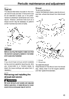
Periodic maintenance and adjustment To install a side cover 1. Place the side cover in the original position, and then tighten the fasteners. 1. Shroud stay Left and right side covers To remove a side cover 1. Remove the shroud. (See the above procedure.) 2. Loosen the fasteners, and then remove the side cover. 2. Install the shroud. TIP Be sure to fit the projection on the rear of the side cover into the hole in the lower side cover. Top cover To remove the top cover 1. Remove the shroud. (See the above procedure.) 2. Remove the screws, and then remove the cable guide. 1. Fastener 2. Right side cover 1. Screw 2. Cable guide 3. 1. Fastener 2. Left side cover Loosen the quick fastener screws, disconnect the main switch coupler and auxiliary DC jack coupler, and then remove the top cover. 44
-
 1
1 -
2
-
3
-
4
-
5
-
6
-
7
-
8
-
9
-
10
-
11
-
12
-
13
-
14
-
15
-
16
-
17
-
18
-
19
-
20
-
21
-
22
-
23
-
24
-
25
-
26
-
27
-
28
-
29
-
30
-
31
-
32
-
33
-
34
-
35
-
36
-
37
-
38
-
39
-
40
-
41
-
42
-
43
-
44
-
 45
45 -
 46
46 -
 47
47 -
 48
48 -
 49
49 -
 50
50 -
 51
51 -
 52
52 -
 53
53 -
 54
54 -
 55
55 -
56
-
57
-
58
-
59
-
60
-
61
-
62
-
63
-
64
-
65
-
66
-
67
-
68
-
69
-
70
-
71
-
72
-
73
-
74
-
75
-
76
-
77
-
78
-
79
-
80
-
81
-
82
-
83
-
84
-
85
-
86
-
87
-
88
-
89
-
90
-
91
-
92
-
93
-
94
-
95
-
96
-
97
-
98
 |
 |
