Tanaka TCG24ECPSL Manual - Page 8
Assembly Procedures
 |
View all Tanaka TCG24ECPSL manuals
Add to My Manuals
Save this manual to your list of manuals |
Page 8 highlights
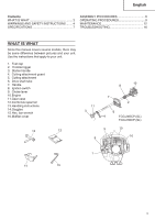
English ASSEMBLY PROCEDURES Installation of handle (Fig. 1) Attach the handle to the drive shaft tube with the angle towards the engine. Adjust the location to the most comfortable position before operation. Make sure to securely attach the handle with the 2 bolts. 3 2 4 1 Fig. 2 Fig. 1 NOTE If your unit has handle location label (1) on drive shaft tube, follow the illustration. Installation of cutting attachment WARNING ● Install the cutting attachment properly and securely as instructed in the handling instructions. If not attached properly or securely, it may come off and cause serious and/or fatal injury. ● Do not install or remove cutting attachments while the engine is running. ● Always use genuine Tanaka cutting attachments and metal fittings. WARNING Do not use metal or plastic blade cutting attachments with loop handle type. Installation of cuttingt attachment guard WARNING ● Do not start or operate unit unless each guard is properly assembled to unit. ● If an incorrect or faulty guard is fitted, this may cause serious personal injury. CAUTION Some cutting attachment guards are equipped with sharp line limiters. Be careful with handling it. Aligning to the position indicated by the guard location label (2), firmly secure the cutting attachment guard to the drive shaft tube with the bolt (3) and guard bracket (4). (Fig. 2) Installation of semi-auto cutting head These models come with the parts installed. 1. Function Automatically feeds more nylon cutting line when it is tapped at low rpm (not greater than 4,500 min-1). Specifications Type of Code No. attaching screw 6696454 Female screw Direction of rotation Counterclockwise Size of attaching screw M10×P1.25LH Applicable nylon cord Cord diameter: 1/8˝ (Φ3.0 mm) Length: 6.5 ft (2 m) Cord diameter: 3/22˝ (Φ2.4 mm) Length: 13 ft (4 m) 2. Precautions ○ The case must be securely attached to the cover. ○ Check the cover, case and other components for cracks or other damage. ○ Check the case and button for wear. If the wear limit mark (5) on the case is no longer visible or there is a hole in the bottom (6) of the button, change the new parts immediately. (Fig. 3) 8
-
 1
1 -
2
-
 3
3 -
 4
4 -
 5
5 -
 6
6 -
 7
7 -
 8
8 -
 9
9 -
 10
10 -
 11
11 -
 12
12 -
 13
13 -
14
-
15
-
16
-
17
-
18
-
19
-
20
-
21
-
22
-
23
-
24
-
25
-
26
-
27
-
28
-
29
-
30
-
31
-
32
-
33
-
34
-
35
-
36
-
37
-
38
-
39
-
40
-
41
-
42
-
43
-
44
-
45
-
46
-
47
-
48
-
49
-
50
-
51
-
52
-
53
-
54
-
55
-
56
 |
 |
