Rane HAL1x Installation Guide - Page 86
DR LCD Screens, HAL LEDs for RADs and DRs, Level, Configuration Mismatch
 |
View all Rane HAL1x manuals
Add to My Manuals
Save this manual to your list of manuals |
Page 86 highlights
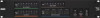
CHAPTER 3: Installing Your HAL System configuration's processing map or it has been added but does not have any Scenarios assigned to it. If all is A-OK with the Pager1, its status LEDs on the front of the device become active. In most cases when first installing the product, the Ready light will turn green. For more details, see "PAGER1 RAD" on page 28. DR LCD Screens: When you first connect the DR, its LCD screen illuminates and displays a spinning wheel and the text Connecting... . What you see next depends on what DR model you are connecting (we are assuming you have loaded a configuration): o DR1: Level along with a level indicator appears. Turning the knob changes the level indicator. o DR2: Depending on the configuration, the DR2 remains blank or displays a list of options. If the DR2 controls are properly linked in the configuration, the DR2 should always display options on its screen. If its controls are not linked, the screen may be blank. If configured as a Selector, either the Selector options appear (if linked) or the screen is blank (not linked). If configured as Toggle or Command controls, the Toggle and/or Command options appear. o DR3: The DR3 behaves the same as a DR2, with a few exceptions. The DR3 always displays Level and a level indicator in its level control (unless it is configured as a List of Levels and there are no levels configured). If configured as a List of Levels, the list is displayed (unless no list has been configured). o If the DR does not match the model configured on the HAL, a flashing exclamation point appears on the LCD screen along with the words: Configuration Mismatch. For more details, see "Task 7: Verify and Troubleshoot Installation" on page 83. NOTE: If you have not loaded a configuration into HAL, this mismatch behavior is what you will see for each DR you install. Why? The HAL is not expecting a DR on the port because none is configured, therefore it reports a configuration mismatch. As soon as you load your configuration, the message will disappear (as long as the configured model matches the physical model detected). o If a P flashes in the upper left corner, this indicates low power, which could be caused by a cable that is too long or crimped incorrectly. o If the Connecting ... message and spinning wheel continue indefinitely, there is likely a problem with the twisted pair responsible for data communications between the DR and the HAL. NOTE: The intensity of the DR's LCD backlight is configurable in the Halogen Hardware Workspace. Also configurable is the length of time that the screen stays lit. For details, see the DR Properties reference topic in the Halogen Help System. HAL LEDs for RADs and DRs: Status information for each RAD and DR port on the HAL and EXP is displayed on the front and rear panel of the HAL/EXP. As long as all four indicators on a RAD are green and as long as the DR is displaying the appropriate information on its LCD screen, there is no need to check these LEDs on the HAL or EXP it is connected to. If a RAD indicator is solid red or the DR is reporting a problem, however, view the corresponding indicators on the HAL/EXP to determine if the problem is originating there. Following are descriptions of the indicators on the HAL: RADs: 80
-
 1
1 -
2
-
3
-
4
-
5
-
6
-
7
-
8
-
9
-
10
-
11
-
12
-
13
-
14
-
15
-
16
-
17
-
18
-
19
-
20
-
21
-
22
-
23
-
24
-
25
-
26
-
27
-
28
-
29
-
30
-
31
-
32
-
33
-
34
-
35
-
36
-
37
-
38
-
39
-
40
-
41
-
42
-
43
-
44
-
45
-
46
-
47
-
48
-
49
-
50
-
51
-
52
-
53
-
54
-
55
-
56
-
57
-
58
-
59
-
60
-
61
-
62
-
63
-
64
-
65
-
66
-
67
-
68
-
69
-
70
-
71
-
72
-
73
-
74
-
75
-
76
-
77
-
78
-
79
-
80
-
 81
81 -
 82
82 -
 83
83 -
 84
84 -
 85
85 -
 86
86 -
 87
87 -
 88
88 -
 89
89 -
 90
90 -
 91
91 -
92
-
93
-
94
-
95
-
96
-
97
-
98
-
99
-
100
-
101
-
102
-
103
-
104
-
105
-
106
-
107
-
108
-
109
-
110
-
111
-
112
-
113
-
114
-
115
-
116
-
117
-
118
-
119
-
120
-
121
-
122
-
123
-
124
-
125
-
126
-
127
-
128
 |
 |
