Rane HAL1x Installation Guide - Page 8
Task 4: Install and connect HAL Expansion Units if needed. - hal1
 |
View all Rane HAL1x manuals
Add to My Manuals
Save this manual to your list of manuals |
Page 8 highlights
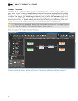
HAL SYSTEM INSTALL GUIDE NOTE: Where this configuration task falls in the installation process is somewhat flexible. If you prefer, you can install and connect the RADs, DRs, and EXPs prior to loading the configuration file. There are advantages, however, in loading the configuration first. Whether or not the configuration is loaded, as long as the HAL is powered on and connected prior to installing the peripheral devices, you can determine immediately upon installing a RAD, DR, or EXP (by observing its status indicators) if it is functioning properly. But if the configuration is also in place, you can immediately determine if the EXP, RAD or DR model you just installed matches the model specified in the HAL configuration (if there's a mismatch, the EXP's front panel LED's flash, the RAD's LEDs flash red and the DR's LCD screen displays Configuration Mismatch). Also, if you have wireless access to the HAL, loading the configuration file early in the process makes it possible to then view the configuration from a laptop as you're installing the RADs, DRs, and EXPs. If you do not have a configuration file and you plan to simply test that the installed equipment can successfully send and receive audio, disregard this recommendation. You will create a simple test configuration after you have installed all of the equipment. Task 3: Pull and terminate the shielded CAT 5e cabling for the EXPs, RADs and DRs. Each EXP, RAD and DR connects to the HAL via a shielded CAT 5e cable. We recommend pulling this cable prior to installing the RADs and DRs. Doing so makes it much easier to troubleshoot their installation. Note that each RAD and DR requires a home run. As noted in the previous task, if the shielded CAT 5e cables are installed and terminated, and the HAL is powered on and connected, you can verify if the RADs and DRs are working properly as soon as you connect them. For details on this task, see "Task 3: Pulling and Terminating shielded CAT 5e Cabling" on page 76. Task 4: Install and connect HAL Expansion Units (if needed). If your system requires one or more Expansion Units (EXPs), you should install and connect them to the HAL before beginning the installation of your Remote Audio Devices (RADs) and Digital Remotes (DRs). This task involves using shielded CAT 5e cable to connect each EXP in a daisy-chained fashion. That is, connecting the first EXP to HAL, connecting the second EXP to the first EXP, and so on. For details, see "Task 4: Installing and Connecting HAL Expansion Units" on page 76. It is important that you install the correct EXP model in each location and in the correct order in the daisy-chain. If you load the HAL configuration prior to installing the EXPs, you can view the status indicators to determine if you have installed the correct model. If the models do not match, the front panel LEDs on the EXP flash. You can also see this status in Halogen's Hardware Workspace. The older HAL1 system used a FireWire based expansion bus. This bus allowed you to connect up to four EXP1 expansion units in a daisy-chained manner. For details see "Task 4 (legacy): Installing and Connecting HAL1 Expansion Units" on page 1. Task 5: Install and connect the individual RADs and DRs. This task involves the connection of the RADs and DRs to the shielded CAT 5e cable, followed by the physical installation of the RADs and DRs into the switchboxes in the wall. A key part of this task is to double-check that you are installing the correct RAD and DR models in each location. The wiring diagram should specify which RAD and DR models go in which locations. Also, if you load the HAL configuration prior to installing the RADs and DRs, you can view the RAD and DR status indicators to determine if you have installed the correct model. If the models do not match, the bottom four LED indicators on the RAD flash red, while the DR LCD screen displays Configuration Mismatch. In addition to verifying that you've installed the correct model, this task involves the verification that the RAD and DR hardware is communicating properly with the HAL. Again, the RAD and DR status indicators provide this information. For details, see "Task 5: Installing and Connecting RADs and DRs" on page 78. 2
-
 1
1 -
2
-
 3
3 -
 4
4 -
 5
5 -
 6
6 -
 7
7 -
 8
8 -
 9
9 -
 10
10 -
 11
11 -
 12
12 -
 13
13 -
14
-
15
-
16
-
17
-
18
-
19
-
20
-
21
-
22
-
23
-
24
-
25
-
26
-
27
-
28
-
29
-
30
-
31
-
32
-
33
-
34
-
35
-
36
-
37
-
38
-
39
-
40
-
41
-
42
-
43
-
44
-
45
-
46
-
47
-
48
-
49
-
50
-
51
-
52
-
53
-
54
-
55
-
56
-
57
-
58
-
59
-
60
-
61
-
62
-
63
-
64
-
65
-
66
-
67
-
68
-
69
-
70
-
71
-
72
-
73
-
74
-
75
-
76
-
77
-
78
-
79
-
80
-
81
-
82
-
83
-
84
-
85
-
86
-
87
-
88
-
89
-
90
-
91
-
92
-
93
-
94
-
95
-
96
-
97
-
98
-
99
-
100
-
101
-
102
-
103
-
104
-
105
-
106
-
107
-
108
-
109
-
110
-
111
-
112
-
113
-
114
-
115
-
116
-
117
-
118
-
119
-
120
-
121
-
122
-
123
-
124
-
125
-
126
-
127
-
128
 |
 |
