Panasonic WU-216MF2U9 - Service Manual - Page 99
INSTALLATION, Fig. 16, Outdoor unit for, cleaning by dry core, Normal outdoor unit
 |
View all Panasonic WU-216MF2U9 manuals
Add to My Manuals
Save this manual to your list of manuals |
Page 99 highlights
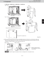
9. CCoommpprreessssoorr 23WAY VVRRFF SSYYSSTTEEMM OOuuttddoooorr UUnniitt RReeppaaiirr PPrroocceedduurreess (13) If the results show that dry core cleaning is still necessary (for example, a color phase of 4.0 or higher)*, return to Step (11) and repeat until the results are normal (including a color phase of 3.5 or less)*. * Color sample sheet for degree of stain CAUTION Perform another dry core replacement after approximately 30 hours of system operation. (14) Perform steps (1) - (4), and remove all dry cores. Then connect the tube between the liquid tube valves and the ball valves. (15) At all outdoor units where dry cores were removed, pressurize with 484 psi (3.34MPa) of nitrogen from the liquid tube service port and check for leaks. (16) After evacuating all nitrogen gas from the tube, apply vacuum to all outdoor units where dry cores were removed until the pressure is -14.7 psig {-101kPa, 5 Torr} or less. (17) INSTALLATION: Refer to the Installation Instructions for further information. 1 Charge with an amount of refrigerant equal to the amount that was recovered. (B) If a ball valve is not installed on the outdoor unit 2 (1) See "4-2-3. Refrigerant recovery procedures (2) : Indoor unit with no ball valve equipped". Perform pump down of the refrigerant from all indoor units and inter-unit tube to the outdoor unit side. (2) Cut the liquid tube at all outdoor units where dry cores will be attached, then attach the dry cores and ball valves as shown in Fig. 16. (3) For the next steps, see the steps (6) - (17) in "(A) If a ball valve is installed on the outdoor unit" on the 3 previous page. Outdoor unit for cleaning by dry core Normal outdoor unit 4 Liquid tube service port (for ø5/16" (ø7.94mm)- dia connector) 5 6 7 Suction tube Liquid tube To indoor unit Discharge tube Balance tube 8 Dry core (bidirectional: for R410A refrigerant) Ball valve Fig. 16 2 - 31 9
-
 1
1 -
2
-
3
-
4
-
5
-
6
-
7
-
8
-
9
-
10
-
11
-
12
-
13
-
14
-
15
-
16
-
17
-
18
-
19
-
20
-
21
-
22
-
23
-
24
-
25
-
26
-
27
-
28
-
29
-
30
-
31
-
32
-
33
-
34
-
35
-
36
-
37
-
38
-
39
-
40
-
41
-
42
-
43
-
44
-
45
-
46
-
47
-
48
-
49
-
50
-
51
-
52
-
53
-
54
-
55
-
56
-
57
-
58
-
59
-
60
-
61
-
62
-
63
-
64
-
65
-
66
-
67
-
68
-
69
-
70
-
71
-
72
-
73
-
74
-
75
-
76
-
77
-
78
-
79
-
80
-
81
-
82
-
83
-
84
-
85
-
86
-
87
-
88
-
89
-
90
-
91
-
92
-
93
-
 94
94 -
 95
95 -
 96
96 -
 97
97 -
 98
98 -
 99
99 -
 100
100 -
 101
101 -
 102
102 -
 103
103 -
 104
104 -
105
-
106
-
107
-
108
-
109
-
110
-
111
-
112
-
113
-
114
-
115
-
116
-
117
-
118
-
119
-
120
-
121
-
122
-
123
-
124
-
125
-
126
-
127
-
128
-
129
-
130
-
131
-
132
-
133
-
134
-
135
-
136
-
137
-
138
-
139
-
140
-
141
-
142
-
143
-
144
-
145
-
146
-
147
-
148
-
149
-
150
-
151
-
152
-
153
-
154
-
155
-
156
-
157
-
158
-
159
-
160
-
161
-
162
-
163
-
164
-
165
-
166
-
167
-
168
-
169
-
170
-
171
-
172
-
173
-
174
-
175
-
176
-
177
-
178
-
179
-
180
-
181
-
182
-
183
-
184
-
185
-
186
-
187
-
188
-
189
-
190
-
191
-
192
-
193
-
194
-
195
-
196
-
197
-
198
-
199
-
200
-
201
-
202
-
203
-
204
-
205
-
206
-
207
-
208
-
209
-
210
-
211
 |
 |
