Panasonic WU-216MF2U9 - Service Manual - Page 77
Recovering Refrigerant, 1. Refrigerant Recovery Procedures from Outdoor Units
 |
View all Panasonic WU-216MF2U9 manuals
Add to My Manuals
Save this manual to your list of manuals |
Page 77 highlights
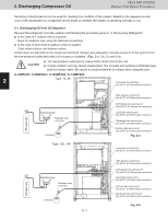
4. RReeccoovveerriinngg RReeffrriiggeerraanntt 23WAY VVRRFF SSYYSSTTEEMM OOuuttddoooorr UUnniitt RReeppaaiirr PPrroocceedduurreess The following equipment and tools are required: Jumper wire with clips, adjustable wrench, set of manifold gauge valves specially designed for refrigerant R410A only, vacuum pump, refrigerant recovery unit, pre-purged refrigerant cylinder for recovery, flathead screwdriver, and outdoor unit maintenance remote controller. 4-1. Refrigerant Recovery Procedures (from Outdoor Units) (1) Turn off the power of the outdoor unit beforehand (at power mains). (2) Fully close all the service valve of the outdoor unit. (3) Connect the outdoor unit's high-pressure and low-pressure outlet ports with the Hi and Lo sides of the manifold gauge valves using hoses. (Figs. 3-a, 3-b) The remaining refrigerant in the faulty outdoor unit may create internal pressure. CAUTION Before connecting hoses, be sure to confirm that each of the manifold gauge valves is 1 tightly closed. Note that the connection ports employ Schrader-type push-to-release valves. (4) Connect the manifold gauge valves, refrigerant recovery unit, and recovery cylinder using hoses. To avoid the entry of air into the refrigerant tube, carry out this connection work carefully. (Figs. 3-a, 3-b) For detailed procedures such as connecting the refrigerant recovery unit with the recovery 2 CAUTION cylinder and methods used for recovery, follow the specific instructions that came with the refrigerant recovery unit. (5) Locate the AP pin (CN24) on the control PCB in the faulty outdoor unit and short them using the clips of the jumper wire. Then restore electrical power to the outdoor unit. By short-circuiting the AP pin (CN24), each solenoid valve in the outdoor unit is forcibly 3 CAUTION opened as soon as power comes on, which releases all remaining refrigerant into the recovery cylinder. Since neglecting this procedure may leave some refrigerant in the system, it is important that you carry out this step. 4 (6) Carry out refrigerant recovery. CAUTION To determine the completion of refrigerant recovery, follow the instructions that CAUTION came with the refrigerant recovery unit. 5 Type: 72, 96 Low-pressure outlet port (for ø5/16" (ø7.94mm)-dia connector) Manifold gauge Lo Hi Refrigerant recovery unit Refrigerant recovery cylinder High-pressure outlet port 6 (for ø5/16" (ø7.94mm)-dia connector) Oil balance tube service port (For ø5/16" (ø7.94mm)-dia connector) Liquid tube service port 7 (for ø5/16" (ø7.94mm)-dia connector) Discharge tube service port (for ø5/16" (ø7.94mm)-dia connector) Suction tube service port (for ø5/16" (ø7.94mm)-dia connector) 8 Fig. 3-a 2 - 9 9
-
 1
1 -
2
-
3
-
4
-
5
-
6
-
7
-
8
-
9
-
10
-
11
-
12
-
13
-
14
-
15
-
16
-
17
-
18
-
19
-
20
-
21
-
22
-
23
-
24
-
25
-
26
-
27
-
28
-
29
-
30
-
31
-
32
-
33
-
34
-
35
-
36
-
37
-
38
-
39
-
40
-
41
-
42
-
43
-
44
-
45
-
46
-
47
-
48
-
49
-
50
-
51
-
52
-
53
-
54
-
55
-
56
-
57
-
58
-
59
-
60
-
61
-
62
-
63
-
64
-
65
-
66
-
67
-
68
-
69
-
70
-
71
-
 72
72 -
 73
73 -
 74
74 -
 75
75 -
 76
76 -
 77
77 -
 78
78 -
 79
79 -
 80
80 -
 81
81 -
 82
82 -
83
-
84
-
85
-
86
-
87
-
88
-
89
-
90
-
91
-
92
-
93
-
94
-
95
-
96
-
97
-
98
-
99
-
100
-
101
-
102
-
103
-
104
-
105
-
106
-
107
-
108
-
109
-
110
-
111
-
112
-
113
-
114
-
115
-
116
-
117
-
118
-
119
-
120
-
121
-
122
-
123
-
124
-
125
-
126
-
127
-
128
-
129
-
130
-
131
-
132
-
133
-
134
-
135
-
136
-
137
-
138
-
139
-
140
-
141
-
142
-
143
-
144
-
145
-
146
-
147
-
148
-
149
-
150
-
151
-
152
-
153
-
154
-
155
-
156
-
157
-
158
-
159
-
160
-
161
-
162
-
163
-
164
-
165
-
166
-
167
-
168
-
169
-
170
-
171
-
172
-
173
-
174
-
175
-
176
-
177
-
178
-
179
-
180
-
181
-
182
-
183
-
184
-
185
-
186
-
187
-
188
-
189
-
190
-
191
-
192
-
193
-
194
-
195
-
196
-
197
-
198
-
199
-
200
-
201
-
202
-
203
-
204
-
205
-
206
-
207
-
208
-
209
-
210
-
211
 |
 |
