Panasonic WU-216MF2U9 - Service Manual - Page 131
Setting the Flap, Continuously
 |
View all Panasonic WU-216MF2U9 manuals
Add to My Manuals
Save this manual to your list of manuals |
Page 131 highlights
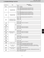
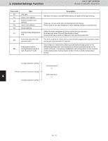
2. Detailed Settings Function 3WAY VRF SYSTEM Remote Controller Functions Item code Item No. Setting data Description DC fan tap operating mode Purpose 0000 Standard Standard (setting at shipment) Fan tap setting (Fan tap change in order to prevent drop in air discharge caused by filter installation) 0001 0003 High ceiling use For low static-pressure filter High ceiling use For low static-pressure filter High ceiling setting 1 (with standard panel) Ultra long-life filter, oil guard panel, ammonia deodorizing filter, optical regenerative deodorizing filter High ceiling setting 2 (with standard panel) (Antibacterial) high-performance filter (90%) (Antibacterial) high-performance filter (65%) Air-cleaning unit, air-cleaning unit + optical regenerative deodorizing filter, deodorant (activated charcoal) filter For air-blocking material For 3-way discharge, when discharge duct is connected 1 0006 For air-blocking material For 2-way discharge 0000 No humidifier output 0001 1 second Humidifier ON time (ON time per 60 0002 2 seconds 2 seconds) 0058 58 seconds 0059 59 seconds 0060 Continuously ON Timer function change 0000 Function disabled prohibit 0001 Function enabled 3 Smudging control 0000 No smudging control Setting the Flap Separately *Only for 4-Way Cassette type Setting the Flap Separately *Only for 4-Way Cassette type Setting the Flap Separately *Only for 4-Way Cassette type Setting the Flap Separately *Only for 4-Way Cassette type 0000 0001 Air discharge port Flap 1 =90 (Motor No. 4) Electrical Flap position component 1 0002 box 2 4 0003 0004 Flap (adjustment for up-down Flap 2 (Motor No. 2) =91 Flap 4 (Motor No. 3) =93 5 4 3 airflow direction) 0005 Flap 3 =92 0006 (Motor No. 1) Setting data Flap position during operation When the flap position is set to 5 Without separate setting 4 or 5 and the unit is in the cooling or dry mode, the flap Swing position is moved to 3 and the Move to position 1 and stay operation is started. 6 Move to position 2 and stay NOTE The flap swings during the Move to position 3 and stay operation under "Setting the Move to position 4 and stay Flap Separately". Move to position 5 and stay At this time, the unselected flaps 7 are moved to the position 1 . 8 4 - 13 9
-
 1
1 -
2
-
3
-
4
-
5
-
6
-
7
-
8
-
9
-
10
-
11
-
12
-
13
-
14
-
15
-
16
-
17
-
18
-
19
-
20
-
21
-
22
-
23
-
24
-
25
-
26
-
27
-
28
-
29
-
30
-
31
-
32
-
33
-
34
-
35
-
36
-
37
-
38
-
39
-
40
-
41
-
42
-
43
-
44
-
45
-
46
-
47
-
48
-
49
-
50
-
51
-
52
-
53
-
54
-
55
-
56
-
57
-
58
-
59
-
60
-
61
-
62
-
63
-
64
-
65
-
66
-
67
-
68
-
69
-
70
-
71
-
72
-
73
-
74
-
75
-
76
-
77
-
78
-
79
-
80
-
81
-
82
-
83
-
84
-
85
-
86
-
87
-
88
-
89
-
90
-
91
-
92
-
93
-
94
-
95
-
96
-
97
-
98
-
99
-
100
-
101
-
102
-
103
-
104
-
105
-
106
-
107
-
108
-
109
-
110
-
111
-
112
-
113
-
114
-
115
-
116
-
117
-
118
-
119
-
120
-
121
-
122
-
123
-
124
-
125
-
 126
126 -
 127
127 -
 128
128 -
 129
129 -
 130
130 -
 131
131 -
 132
132 -
 133
133 -
 134
134 -
 135
135 -
 136
136 -
137
-
138
-
139
-
140
-
141
-
142
-
143
-
144
-
145
-
146
-
147
-
148
-
149
-
150
-
151
-
152
-
153
-
154
-
155
-
156
-
157
-
158
-
159
-
160
-
161
-
162
-
163
-
164
-
165
-
166
-
167
-
168
-
169
-
170
-
171
-
172
-
173
-
174
-
175
-
176
-
177
-
178
-
179
-
180
-
181
-
182
-
183
-
184
-
185
-
186
-
187
-
188
-
189
-
190
-
191
-
192
-
193
-
194
-
195
-
196
-
197
-
198
-
199
-
200
-
201
-
202
-
203
-
204
-
205
-
206
-
207
-
208
-
209
-
210
-
211
 |
 |
