Panasonic WU-216MF2U9 - Service Manual - Page 57
Invalid P, 1=Heating airflow prevention mode
 |
View all Panasonic WU-216MF2U9 manuals
Add to My Manuals
Save this manual to your list of manuals |
Page 57 highlights
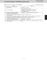
14. Detailed Settings in EEPROM of Outdoor Unit 3WAY VRF SYSTEM Control Functions Never use the DN code unlisted in the following table. (P) : Factory preset mode DN Item Setting No. AC Actuation of solenoid valve kit (EP closed) 0=Invalid (P), 1=Valid 0=Continuously set OFF (P) C1 O2 output change 1=Refrigerant leak prevention (normal OFF) 2=Refrigerant leak prevention (normal ON) 3=Pumpdown control CD Setting at heating thermostat OFF 0=Invalid (P) , 1=Heating airflow prevention mode Indoor fan mode setting when in DD discharge tube accumulated refrigerant 0=Invalid , 1=stop (P) , 2=LL recovery control DE Discharge tube accumulated refrigerant -25=-13°F (-25°C), -20=-4°F (-20°C), -15=5°F (-15°C) ,,,,, recovery control permission temperature 40=104°F (40°C) ,,,,, 55=131°F (55°C) 1 E1 Discharge air temperature control with thermostat OFF additional time -20=-20 min , -19=-19 min ,,,,, 0=0 min (P) ,,,,, 10=10 min ED Indoor unit fan selection when in cooling 0=Invalid (P) , 1=stop , 2=LL , 3=interval operation , 4=never thermostat OFF use 2 3 4 5 6 7 8 1 - 49 9
-
 1
1 -
2
-
3
-
4
-
5
-
6
-
7
-
8
-
9
-
10
-
11
-
12
-
13
-
14
-
15
-
16
-
17
-
18
-
19
-
20
-
21
-
22
-
23
-
24
-
25
-
26
-
27
-
28
-
29
-
30
-
31
-
32
-
33
-
34
-
35
-
36
-
37
-
38
-
39
-
40
-
41
-
42
-
43
-
44
-
45
-
46
-
47
-
48
-
49
-
50
-
51
-
 52
52 -
 53
53 -
 54
54 -
 55
55 -
 56
56 -
 57
57 -
 58
58 -
 59
59 -
 60
60 -
 61
61 -
 62
62 -
63
-
64
-
65
-
66
-
67
-
68
-
69
-
70
-
71
-
72
-
73
-
74
-
75
-
76
-
77
-
78
-
79
-
80
-
81
-
82
-
83
-
84
-
85
-
86
-
87
-
88
-
89
-
90
-
91
-
92
-
93
-
94
-
95
-
96
-
97
-
98
-
99
-
100
-
101
-
102
-
103
-
104
-
105
-
106
-
107
-
108
-
109
-
110
-
111
-
112
-
113
-
114
-
115
-
116
-
117
-
118
-
119
-
120
-
121
-
122
-
123
-
124
-
125
-
126
-
127
-
128
-
129
-
130
-
131
-
132
-
133
-
134
-
135
-
136
-
137
-
138
-
139
-
140
-
141
-
142
-
143
-
144
-
145
-
146
-
147
-
148
-
149
-
150
-
151
-
152
-
153
-
154
-
155
-
156
-
157
-
158
-
159
-
160
-
161
-
162
-
163
-
164
-
165
-
166
-
167
-
168
-
169
-
170
-
171
-
172
-
173
-
174
-
175
-
176
-
177
-
178
-
179
-
180
-
181
-
182
-
183
-
184
-
185
-
186
-
187
-
188
-
189
-
190
-
191
-
192
-
193
-
194
-
195
-
196
-
197
-
198
-
199
-
200
-
201
-
202
-
203
-
204
-
205
-
206
-
207
-
208
-
209
-
210
-
211
 |
 |
