Panasonic WU-216MF2U9 - Service Manual - Page 37
Minimum 1 minute - Maximum 20 minutes Until Tc, All Indoor Units
 |
View all Panasonic WU-216MF2U9 manuals
Add to My Manuals
Save this manual to your list of manuals |
Page 37 highlights
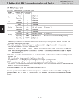
77..TTuubebeReRfreigfreirgaenrtaRnetcRoveecroyvCeornytrCool ntrol 3WAY VRF SYSTEM Con3tWroAlYFuSnYcStTioEnMs Control Functions Control when outdoor unit heat exchanger is acting as an evaporator (when all units are in heating mode or at start of mixed operation when heating load is high) Control time Minimum 1 minute - Maximum 20 minutes (Until Tc >_ 95°F (35°C)) Outdoor units All outdoor units operate at maximum horsepower. Expansion valve Valves at all indoor units operate at 250 pulses. Solenoid valve kit Valve kits at all indoor units operate in heating mode (ON status) All Indoor Units Fan As for heating thermostat ON indoor units, follow the indoor unit control system. Fan and cooling (thermostat ON/OFF) and/or heating (thermostat OFF) operation of indoor unit will be stopped. The fan speed of the heating thermostat OFF Concealed Duct - High 1 Static type indoor unit (Type E1) is changed to LL. * When the above operation is finished, normal operation starts at the horsepower determined by the indoor units where thermostats are ON. * When the horsepower of heating thermostat ON still remains greater than that of cooling thermostat ON during 2 control mentioned above, normal control is performed without stopping the compressor. * When the horsepower of cooling thermostat ON is getting greater than that of heating thermostat ON during control mentioned above, once stop the outdoor unit after completion of control. Then change the heat exchanger acting as an evaporator to a condenser and resume the operation. 3 4 5 6 7 8 1 - 29 9
-
 1
1 -
2
-
3
-
4
-
5
-
6
-
7
-
8
-
9
-
10
-
11
-
12
-
13
-
14
-
15
-
16
-
17
-
18
-
19
-
20
-
21
-
22
-
23
-
24
-
25
-
26
-
27
-
28
-
29
-
30
-
31
-
 32
32 -
 33
33 -
 34
34 -
 35
35 -
 36
36 -
 37
37 -
 38
38 -
 39
39 -
 40
40 -
 41
41 -
 42
42 -
43
-
44
-
45
-
46
-
47
-
48
-
49
-
50
-
51
-
52
-
53
-
54
-
55
-
56
-
57
-
58
-
59
-
60
-
61
-
62
-
63
-
64
-
65
-
66
-
67
-
68
-
69
-
70
-
71
-
72
-
73
-
74
-
75
-
76
-
77
-
78
-
79
-
80
-
81
-
82
-
83
-
84
-
85
-
86
-
87
-
88
-
89
-
90
-
91
-
92
-
93
-
94
-
95
-
96
-
97
-
98
-
99
-
100
-
101
-
102
-
103
-
104
-
105
-
106
-
107
-
108
-
109
-
110
-
111
-
112
-
113
-
114
-
115
-
116
-
117
-
118
-
119
-
120
-
121
-
122
-
123
-
124
-
125
-
126
-
127
-
128
-
129
-
130
-
131
-
132
-
133
-
134
-
135
-
136
-
137
-
138
-
139
-
140
-
141
-
142
-
143
-
144
-
145
-
146
-
147
-
148
-
149
-
150
-
151
-
152
-
153
-
154
-
155
-
156
-
157
-
158
-
159
-
160
-
161
-
162
-
163
-
164
-
165
-
166
-
167
-
168
-
169
-
170
-
171
-
172
-
173
-
174
-
175
-
176
-
177
-
178
-
179
-
180
-
181
-
182
-
183
-
184
-
185
-
186
-
187
-
188
-
189
-
190
-
191
-
192
-
193
-
194
-
195
-
196
-
197
-
198
-
199
-
200
-
201
-
202
-
203
-
204
-
205
-
206
-
207
-
208
-
209
-
210
-
211
 |
 |
