Panasonic WU-216MF2U9 - Service Manual - Page 142
How to Set on PC Board, Fig. 3, Table 3 External static pressure
 |
View all Panasonic WU-216MF2U9 manuals
Add to My Manuals
Save this manual to your list of manuals |
Page 142 highlights
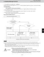
2. Detailed Settings Function 1-4. How to Set on PC Board 1. Turn off the power breaker to halt the supply of electricity to the PC board. 2. Open the cover of the electrical box and confirm that there is the indoor unit control PC board in it. When using with high static pressure mode, set the indoor unit control PC board as shown in Fig. 3. 3. Connect the short circuit connector to the short circuit pin TP3 (2P: Yellow) of the indoor unit control board. l In the case of wired remote control setting, do 1 not use the short circuit connector. 2 3WAY VRF SYSTEM Remote Controller Functions Table 3 External static pressure Type 7 9 12 15 18 Standard in.WC 0.04 0.06 0.06 0.06 0.06 Pa 10 15 15 15 15 in.WC 0.12 0.12 0.16 0.16 0.16 High static pressure Pa 30 30 40 40 40 White Yellow Red T5A L250V IC001 IC010 TP6 TP3 TP1 CHK CN062 DISP CN063 TEST CN064 EXCT CN073 JP001 FAN-TAP TP6 TP3TP1 CN044 EMG CN040 OC CN041 RC Fig. 3 3 4 5 6 7 8 9 4 - 24
-
 1
1 -
2
-
3
-
4
-
5
-
6
-
7
-
8
-
9
-
10
-
11
-
12
-
13
-
14
-
15
-
16
-
17
-
18
-
19
-
20
-
21
-
22
-
23
-
24
-
25
-
26
-
27
-
28
-
29
-
30
-
31
-
32
-
33
-
34
-
35
-
36
-
37
-
38
-
39
-
40
-
41
-
42
-
43
-
44
-
45
-
46
-
47
-
48
-
49
-
50
-
51
-
52
-
53
-
54
-
55
-
56
-
57
-
58
-
59
-
60
-
61
-
62
-
63
-
64
-
65
-
66
-
67
-
68
-
69
-
70
-
71
-
72
-
73
-
74
-
75
-
76
-
77
-
78
-
79
-
80
-
81
-
82
-
83
-
84
-
85
-
86
-
87
-
88
-
89
-
90
-
91
-
92
-
93
-
94
-
95
-
96
-
97
-
98
-
99
-
100
-
101
-
102
-
103
-
104
-
105
-
106
-
107
-
108
-
109
-
110
-
111
-
112
-
113
-
114
-
115
-
116
-
117
-
118
-
119
-
120
-
121
-
122
-
123
-
124
-
125
-
126
-
127
-
128
-
129
-
130
-
131
-
132
-
133
-
134
-
135
-
136
-
 137
137 -
 138
138 -
 139
139 -
 140
140 -
 141
141 -
 142
142 -
 143
143 -
 144
144 -
 145
145 -
 146
146 -
 147
147 -
148
-
149
-
150
-
151
-
152
-
153
-
154
-
155
-
156
-
157
-
158
-
159
-
160
-
161
-
162
-
163
-
164
-
165
-
166
-
167
-
168
-
169
-
170
-
171
-
172
-
173
-
174
-
175
-
176
-
177
-
178
-
179
-
180
-
181
-
182
-
183
-
184
-
185
-
186
-
187
-
188
-
189
-
190
-
191
-
192
-
193
-
194
-
195
-
196
-
197
-
198
-
199
-
200
-
201
-
202
-
203
-
204
-
205
-
206
-
207
-
208
-
209
-
210
-
211
 |
 |
