LiftMaster CAPXM Installation Manual - English French Spanish Manufactured Pri - Page 22
Wiring Diagram, local codes BEFORE installation.
 |
View all LiftMaster CAPXM manuals
Add to My Manuals
Save this manual to your list of manuals |
Page 22 highlights
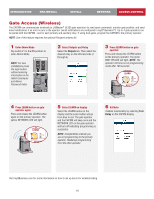
Wiring Diagram Not responsible for conflicts between the information listed in the wiring diagram and the requirements of your local building codes. The information is for suggested use ONLY. Check your local codes BEFORE installation. Speaker Microphone Faceplate/Screen Red Black White Red Black Touch Panel (Back of Control Board) Optional External Wi-Fi® Antenna Internal Wi-Fi® Antenna Not to scale Display Data (Back of Control Board) Postal Lock Switch Purple White Power Supply Red Black Yellow White Green Black USB Optional MyQ® Cable Extension Kit Ethernet Ethernet Connection USB Camera Door Board 22
-
 1
1 -
2
-
3
-
4
-
5
-
6
-
7
-
8
-
9
-
10
-
11
-
12
-
13
-
14
-
15
-
16
-
 17
17 -
 18
18 -
 19
19 -
 20
20 -
 21
21 -
 22
22 -
 23
23 -
 24
24 -
 25
25 -
 26
26 -
 27
27 -
28
-
29
-
30
-
31
-
32
-
33
-
34
-
35
-
36
-
37
-
38
-
39
-
40
-
41
-
42
-
43
-
44
-
45
-
46
-
47
-
48
-
49
-
50
-
51
-
52
-
53
-
54
-
55
-
56
-
57
-
58
-
59
-
60
-
61
-
62
-
63
-
64
-
65
-
66
-
67
-
68
-
69
-
70
-
71
-
72
-
73
-
74
-
75
-
76
-
77
-
78
-
79
-
80
 |
 |

22
Wiring Diagram
Not responsible for conflicts between the information listed in
the wiring diagram and the requirements of your local building
codes. The information is for suggested use ONLY. Check your
local codes BEFORE installation.
Yellow
White
Green
Black
White
Red
Black
Red
Black
Purple
Not to scale
(Back of Control Board)
(Back of Control Board)
Red
Ethernet
USB
Black
White
Door Board
USB Camera
Postal Lock Switch
Power Supply
Ethernet Connection
Internal Wi-Fi
®
Antenna
Optional External
Wi-Fi
®
Antenna
Optional MyQ
®
Cable Extension Kit
Microphone
Speaker
Faceplate/Screen
Display Data
Touch Panel