Invacare ROZE Owners Manual
Invacare ROZE Manual
 |
View all Invacare ROZE manuals
Add to My Manuals
Save this manual to your list of manuals |
Invacare ROZE manual content summary:
- Invacare ROZE | Owners Manual - Page 1
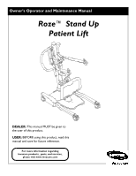
Owner's Operator and Maintenance Manual Roze™ Stand Up Patient Lift DEALER: This manual MUST be given to the user of this product. USER: BEFORE using this product, read this manual and save for future reference. For more information regarding Invacare products, parts, and services, please visit www. - Invacare ROZE | Owners Manual - Page 2
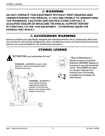
AND UNDERSTANDING THIS MANUAL. IF YOU ARE UNABLE TO UNDERSTAND THE WARNINGS, CAUTIONS AND INSTRUCTIONS CONTACT A QUALIFIED DEALER OR INVACARE TECHNICAL SUPPORT BEFORE ATTEMPTING TO site. Contact your local waste management company for information. Roze™ Stand Up Patient Lift 2 Part No. 1150703 - Invacare ROZE | Owners Manual - Page 3
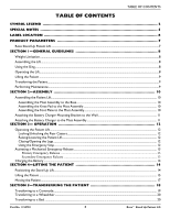
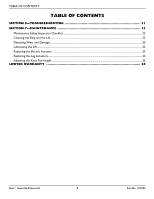
4-LIFTING THE PATIENT 14 Positioning the Stand Up Lift ...14 Lifting the Patient ...15 Moving the Patient ...17 SECTION 5-TRANSFERRING THE PATIENT 18 Transferring to a Commode...19 Transferring to a Wheelchair...20 Transferring to a Bed ...20 Part No. 1150703 3 Roze™ Stand Up Patient Lift - Invacare ROZE | Owners Manual - Page 4
Inspection Checklist...22 Cleaning the Sling and the Lift...23 Detecting Wear and Damage...23 Lubricating the Lift ...23 Replacing the Electric Actuator ...23 Replacing the Leg Actuators ...24 Adjusting the Knee Pad Height ...25 LIMITED WARRANTY 26 Roze™ Stand Up Patient Lift 4 Part No. 1150703 - Invacare ROZE | Owners Manual - Page 5
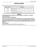
SPECIAL NOTES SPECIAL NOTES Signal words are used in this manual and apply to hazards or unsafe practices which could result in personal injury transmission is in progress. MAINTENANCE Maintenance MUST be performed ONLY by qualified personnel. Part No. 1150703 5 Roze™ Stand Up Patient Lift - Invacare ROZE | Owners Manual - Page 6
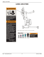
LABEL LOCATION LABEL LOCATION NOTE: Sling Size label is located on cross bar (not shown). Sling Sizes Small Medium Large Navy Purple Green XL Blue WARNING USE ONLY INVACARE SLINGS and LIFT ACCESSORIES. XXL 1154553 REV. A Black Roze™ Stand Up Patient Lift 6 Part No. 1150703 - Invacare ROZE | Owners Manual - Page 7
PRODUCT PARAMETERS Roze Stand Up Patient Lift Height at Sling Hook-up - MAX.: Height at Sling Hook-up - MIN.: Base Width OPEN: Base Width CLOSED: Base Height (Clearance): Base Length: Overall Height: Overall Length: Overall Width: Caster Size (FRONT/REAR): Sling Options: Sling Material: Weight - Invacare ROZE | Owners Manual - Page 8
read the instructions in this Owner's Manual, observe a trained team of experts perform the lifting procedures and then perform the entire lift procedure several times with proper supervision and a capable individual acting as a patient. Invacare Stand Assist and Transfer slings are specifically - Invacare ROZE | Owners Manual - Page 9
, the parts MUST be replaced. Perform this inspection every six months thereafter. DO NOT overtighten mounting hardware. This will damage mounting brackets. Casters and axle bolts require inspections every six months to check for tightness and wear. Part No. 1150703 9 Roze™ Stand Up Patient Lift - Invacare ROZE | Owners Manual - Page 10
Put the tube of the mast assembly into the hole in the base. 7. While supporting the mast assembly, tighten the bottom plastic knob. 8. Screw the top plastic knob place) Roze™ Stand Up Patient Lift Bottom Mounting Bolt FIGURE 2.3 Assembling the Foot Plate to the Mast Assembly 10 Part No. 1150703 - Invacare ROZE | Owners Manual - Page 11
make sure to unplug the battery charger from the wall outlet BEFORE using the patient lift. Failure to unplug the battery charger may result in injury or damage. NOTE: on mast assembly Part No. 1150703 FIGURE 2.5 Attaching the Battery Charger to the Mast Assembly 11 Roze™ Stand Up Patient Lift - Invacare ROZE | Owners Manual - Page 12
Up Button Legs Open Button Down Button Legs Close Button Hand Control DETAIL "C" - EMERGENCY STOP Emergency Button Push in to stop, turn clockwise to reset. Roze™ Stand Up Patient Lift FIGURE 3.1 Operating the Patient Lift 12 Part No. 1150703 - Invacare ROZE | Owners Manual - Page 13
NOTE: For this procedure, refer to FIGURE 3.4. NOTE: Invacare recommends the battery be recharged daily to prolong battery life. click. Part No. 1150703 13 An audible "click" will be heard when properly installed (STEPS 3 and 6) FIGURE 3.4 Primary Emergency Release Roze™ Stand Up Patient Lift - Invacare ROZE | Owners Manual - Page 14
of moving parts to avoid injury. Invacare patient slings are made specifically for use with Invacare patient lifts. For the safety of the patient, DO NOT intermix patient slings and patient lifts of different manufacturers. Individuals that use the standing patient sling MUST be able to support the - Invacare ROZE | Owners Manual - Page 15
the patient upright then move legs over the side of the bed. 1. Instruct the patient to hold onto the hand grips on both sides of the stand up lift (Detail "A" of FIGURE 4.2). 2. Instruct the patient to lean back into the standing or transfer sling. Part No. 1150703 15 Roze™ Stand Up Patient Lift - Invacare ROZE | Owners Manual - Page 16
making the patient feel more secure and the lift easier to move. DETAIL "A" - STAND UP LIFT DETAIL "B" - WHEEL LOCK Mast Handle Wheel Lock Handgrip Casters Knee Pad DETAIL "C" - LIFTING THE PATIENT Foot Plate Sling FIGURE 4.2 Lifting the Patient Roze™ Stand Up Patient Lift 16 Part No - Invacare ROZE | Owners Manual - Page 17
maximum open position. If not, press the OPEN LEGS button on the hand control to move the legs to the maximum open position. 2. Move the stand up lift away from the surface they were lifted from. 3. Slowly move the patient to the desired surface. Part No. 1150703 17 Roze™ Stand Up Patient Lift - Invacare ROZE | Owners Manual - Page 18
each time the sling is removed and replaced to ensure that it is properly attached before the patient is removed from a surface. The use of one assistant is based on the evaluation of the health care professional for each individual case. Roze™ Stand Up Patient Lift 18 Part No. 1150703 - Invacare ROZE | Owners Manual - Page 19
the rear casters and pull the stand up lift away from the commode. 10. When complete, recheck the sling for correct attachments. 11. To lift the patient from the commode. SECTION 5-TRANSFERRING THE PATIENT FIGURE 5.1 Transferring to a Commode Part No. 1150703 19 Roze™ Stand Up Patient Lift - Invacare ROZE | Owners Manual - Page 20
stand up lift. 5. Instruct the patient to lift their feet off of the foot plate. NOTE: Assist the patient if necessary. 6. Remove the standing or transport sling from around the patient. 7. Unlock the rear casters and pull the stand up lift away from the bed. Roze™ Stand Up Patient Lift 20 Part - Invacare ROZE | Owners Manual - Page 21
RED emergency stop button pressed IN. SECTION 6-TROUBLESHOOTING SOLUTION Refer to Lubricating the Lift on page 23. Charge batteries. Refer to 24. NOTE: If problems are not remedied by the suggested means, please contact your dealer or Invacare. Part No. 1150703 21 Roze™ Stand Up Patient Lift - Invacare ROZE | Owners Manual - Page 22
the maintenance procedures described in this manual to keep your patient lift in continuous service. The Invacare Patient Lift is designed to provide a maximum of safe, efficient and satisfactory service with minimum care and maintenance. All parts of the Invacare Lift are made of the best grades - Invacare ROZE | Owners Manual - Page 23
mounting bracket. B. Remove the screw, washer, bearing, nylon washer, bushing, nylon washer, bearing, washer, flat washer, and nut. 4. To replace the electric actuator, reverse STEPS 1‐3. Part No. 1150703 23 Roze™ Stand Up Patient Lift - Invacare ROZE | Owners Manual - Page 24
. If both legs do not operate properly, perform this replacement procedure on both sides of the base. 5. Locate and disconnect the leg actuator lead wires. Roze™ Stand Up Patient Lift 24 Part No. 1150703 - Invacare ROZE | Owners Manual - Page 25
that will be comfortable for the patient and will provide the necessary support. Engage the quick release knob into position until the knee pad is secure in place. Knee Pad Quick Release Knob CLOSE Part No. 1150703 FIGURE 7.3 Adjusting the Knee Pad Height 25 Roze™ Stand Up Patient Lift - Invacare ROZE | Owners Manual - Page 26
INVACARE'S CONTROL, AND SUCH EVALUATION WILL BE SOLELY DETERMINED BY INVACARE. THE WARRANTY SHALL NOT APPLY TO PROBLEMS ARISING FROM NORMAL WEAR OR FAILURE TO ADHERE TO THE INSTRUCTIONS IN THIS MANUAL WITH STATE OR PROVINCIAL LAWS AND REQUIREMENTS. Roze™ Stand Up Patient Lift 26 Part No. 1150703 - Invacare ROZE | Owners Manual - Page 27
Lève-personne Roze™ DÉTAILLANT : Ce manuel DOIT être remis à l'utilisateur du lève-personne. UTILISATEUR : Avant d'utiliser cet appareil, lisez ce manuel et gardez-le à titre de référence. Pour de plus amples renseignements sur les produits, les pièces et les services d'Invacare, consultez notre - Invacare ROZE | Owners Manual - Page 28
des produits Invacare. LÉGENDE DES SYMBOLES « ATTENTION, veuillez-vous référer aux directives d'utilisation. » MISE EN GARDE - Tenez TOUJOURS compte des bras du lève-personne. Des blessures au patient et/ou région pour obtenir de plus amples renseignements. Lève-personne Roze™ 28 Part No. 1150703 - Invacare ROZE | Owners Manual - Page 29
du lève-personne...40 Le soulèvement du patient...41 Déplacer le patient...43 SECTION 5-LE TRANSFERT D'UN PATIENT 44 Transfert vers une toilette...45 Le transfert vers un fauteuil roulant ...46 Transfert du patient vers un lit ...46 SECTION 6-DÉPANNAGE 47 Part No. 1150703 29 Lève-personne Roze™ - Invacare ROZE | Owners Manual - Page 30
Remplacement de l'actionneur électrique ...49 Remplacement des actionneurs de jambes ...50 Réglage de la hauteur du coussin pour genoux...51 GARANTIE LIMITÉE 52 Lève-personne Roze™ 30 Part No. 1150703 - Invacare ROZE | Owners Manual - Page 31
le bouton d'urgence rouge. N'ÉTAIGNEZ PAS le bouton d'urgence rouge lorsque la transmission est en cours. ENTRETIEN Seule une personne qualifiée DOIT exécuter l'entretien. Part No. 1150703 31 Lève-personne Roze™ - Invacare ROZE | Owners Manual - Page 32
rechanges pour le lève-patient, N'UTILISEZ QUE les composants adéquats. Se référer au manuel de l'utilisateur pour les procédures d'entretien périodiques. Customer Service: 1-800-333-6900 DE LEVAGE AUTHENTIQUES XXL INVACARE. Noir 1160882 REV. A Lève-personne Roze™ 32 Part No. 1150703 - Invacare ROZE | Owners Manual - Page 33
PARAMÈTRES DU PRODUIT PARAMÈTRES DU PRODUIT Lève-personne Roze Hauteur du point d'ancrage de la toile - MAX. : Hauteur du point d'ancrage de la toile - MIN. : 240V CC 29,5V CC Max. 6 heures Oui Anti-piégeage *100-200 cycles par chargement 3 ans/2 ans Oui Part No. 1150703 33 Lève-personne Roze™ - Invacare ROZE | Owners Manual - Page 34
de plus amples instructions. Le lève‐personne dʹInvacare nʹest PAS un composants de lʹascenseur patient pour les signes Roze est de 450 lb. Assemblage du lève-personne NE serrez PAS excessivement lʹéquipement de montage. Vous risquez dʹabîmer les supports mesure de supporter une part importante de - Invacare ROZE | Owners Manual - Page 35
patient Avant de placer les jambes du lève‐personne autour du patient, assurez‐vous que les pieds du patient patient. Cette pratique pourrait faire basculer le lève‐personne et mettre le patient et les préposés en danger. Invacare dʹabaisser le patient dans le les supports de fixation. Les - Invacare ROZE | Owners Manual - Page 36
retiré du lève‐personne du patient pour lʹentreposage ou le transport. Le coussin pour genoux DOIT être solidement fixé au montage du mât avant son utilisation. Support de fixation du coussin de genoux FIGURE 2.3 Montage du repose-pieds au montage du mât Lève-personne Roze™ 36 Part No. 1150703 - Invacare ROZE | Owners Manual - Page 37
1. Placez le support de chargeur de le mur. 5. Placez le support de chargeur de pile au support de chargeur de pile et dans le mur. Resserrez fermement. Support support de chargeur de pile au mur 8. Placez le chargeur de pile sur le support de fondation. 4. Placez le support de chargeur de pile sur - Invacare ROZE | Owners Manual - Page 38
PAS de transférer un patient sans l'accord de son médecin, d'un infirmier ou d'un préposé. Lisez attentivement les instructions contenues dans le manuel d' tournez dans le sens horaire pour réinitialiser. Lève-personne Roze™ FIGURE 3.1 Le fonctionnement du lève-personne 38 Part No. 1150703 - Invacare ROZE | Owners Manual - Page 39
référer à la FIGURE 3.4. REMARQUE:Invacare recommande de charger la pile chaque jour . Enfoncez la partie supérieure de la pile contre le support de fixation jusquʹà ce quʹun déclic se fasse entendre la partie supérieure de la pile contre le support de fixation jusquʹà ce quʹun déclic se fasse - Invacare ROZE | Owners Manual - Page 40
ées avec les lève-personnes d'Invacare. Afin d'assurer la sécurité du patient, N'UTILISEZ PAS de toiles ou de lève-personnes provenant de différents fabricants. Les personnes qui utilisent la toile station debout DOIVENT être en mesure de supporter une part importante de leur propre poids sinon - Invacare ROZE | Owners Manual - Page 41
és avant de déplacer le patient. Les toiles Invacare sont conçues spécifiquement pour être utilisées avec les lève-personnes d'Invacare. Afin d'assurer la sécurité du patient, N'UTILISEZ PAS de toiles ou de lève-personnes provenant de différents fabricants. Part No. 1150703 41 Lève-personne Roze™ - Invacare ROZE | Owners Manual - Page 42
). Le lève‐personne doit supporter tout le poids du patient (Détail « C » de la FIGURE 4.2). REMARQUE: Le champ de gravité inférieur offre une stabilité pour que le patient se sente plus en sécurité et que le lève‐personne soit plus facile à déplacer. Lève-personne Roze™ 42 Part No. 1150703 - Invacare ROZE | Owners Manual - Page 43
le plus possible afin d'assurer une stabilité et une sécurité supérieures. Si le patient se trouve dans une toile et il s'avère nécessaire de le faire passer dans un la surface de soulèvement. 3. Déplacez le patient lentement vers la surface désirée. Part No. 1150703 43 Lève-personne Roze™ - Invacare ROZE | Owners Manual - Page 44
le patient. Si le patient, patient patient. Les bras du patient devraient se trouver à l'extérieur des courroies. N'UTILISEZ PAS de toiles ou de lève-personnes de différents fabricants. Les toiles Invacare Si le patient est dans une soulevez le patient hors du placer le patient d'un endroit à - Invacare ROZE | Owners Manual - Page 45
sur le lève‐personne. ii. Soulevez les jambes du patients et retirez les supports de cuisses sous le patient. iii. Si désiré, décrochez la toile de le patient de la toilette. SECTION 5-LE TRANSFERT D'UN PATIENT FIGURE 5.1 Transfert vers une toilette Part No. 1150703 45 Lève-personne Roze™ - Invacare ROZE | Owners Manual - Page 46
‐personne. 5. Dites au patient de lever les pieds du repose‐pieds. REMARQUE: Aidez le patient à le faire au besoin. 6. Retirez la toile debout ou de transport autour du patient. 7. Déverrouillez les roulettes arrière et éloignez le lève‐personne du lit. Lève-personne Roze™ 46 Part No. 1150703 - Invacare ROZE | Owners Manual - Page 47
Remplacement des actionneurs de jambes on page 50. REMARQUE: Si les problèmes persistent à la suite des actions suggérées, communiquez avec votre détaillant ou Invacare. Part No. 1150703 47 Lève-personne Roze™ - Invacare ROZE | Owners Manual - Page 48
afin de vous assurer qu'elles soi- ent bien en place et que le patient est en sécurité. X X X Assurez-vous que le tissu de la toile à sa conception supérieure, le lève‐personne dʹInvacare vous offre un service sécuritaire et efficace à la hauteur de vos attentes Roze™ 48 Part No. 1150703 - Invacare ROZE | Owners Manual - Page 49
réparé. La lubrification du lève-personne Le lève‐personne dʹInvacare est conçu pour un entretien minimal. Toutefois, la vérification partie inférieure de lʹactionneur de la membrure au support de fixation de lʹactionneur de la membrure. A. Retirez 1 à 3. Part No. 1150703 49 Lève-personne Roze™ - Invacare ROZE | Owners Manual - Page 50
mécanisme de positionnement Dirige Trou Bague Rondelle Bouchon Actionneur du bras du support de fixation Rondelle Rondelles plate en nylon Bouchon Rapport Écrou Rondelle BAS Rapport Repérez et débranchez les fils de lʹactionneur de la jambe. Lève-personne Roze™ 50 Part No. 1150703 - Invacare ROZE | Owners Manual - Page 51
lʹactionneur de la jambe au support de la jambe. 8. Au é, le genou du patient entre en contact direct patient et qui lui procure le support approprié. Mettez la poignée de blocage rapide en position jusquʹà ce que le coussin de genoux soit bien fixé en place. Knee Pad Quick Release Knob CLOSE Part - Invacare ROZE | Owners Manual - Page 52
gard du service au titre de la garantie, écrivez directement à Invacare à l' préalable de notre part. Les envois contre remboursement INVACARE. UNE TELLE ÉVALUATION NE SERA FAITE QUE PAR INVACARE. CETTE GARANTIE NE S'APPLIQUE PAS À DES PROBLÈMES DUS À L'USURE NORMALE OU AU NON-RESPECT DES INSTRUCTIONS
-
 1
1 -
 2
2 -
 3
3 -
 4
4 -
 5
5 -
 6
6 -
 7
7 -
8
-
9
-
10
-
11
-
12
-
13
-
14
-
15
-
16
-
17
-
18
-
19
-
20
-
21
-
22
-
23
-
24
-
25
-
26
-
27
-
28
-
29
-
30
-
31
-
32
-
33
-
34
-
35
-
36
-
37
-
38
-
39
-
40
-
41
-
42
-
43
-
44
-
45
-
46
-
47
-
48
-
49
-
50
-
51
-
52
 |
 |

Owner’s Operator and Maintenance Manual
DEALER:
This manual MUST be given to
the user of this product.
USER:
BEFORE using this product, read this
manual and save for future reference.
For more information regarding
Invacare products,
parts, and services,
please visit www.invacare.com
Roze™ Stand Up
Patient Lift